Utilization start interval prediction device and utilization start interval prediction method
a technology of start interval and prediction device, which is applied in the direction of electric devices, process and machine control, instruments, etc., can solve the problems of rising power consumption in households, and achieve the effect of reducing user load and reducing power saving
- Summary
- Abstract
- Description
- Claims
- Application Information
AI Technical Summary
Benefits of technology
Problems solved by technology
Method used
Image
Examples
embodiment 1
[0095]A user's sense of values is various, which means that there is a user who wants to avoid load imposition while there is also a user who wants to save power as much as possible. Therefore, in Embodiment 1, a method of displaying, to a user, a relationship between user load and power saving effect, with respect to a plurality of prediction results obtained by predicting a prediction interval by varying a variable value which is a parameter used for predicting a prediction interval, will be described with reference to specific examples.
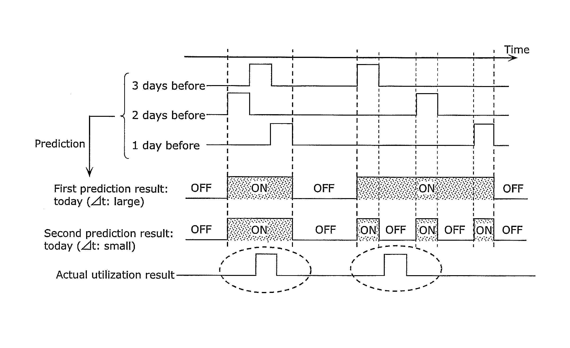
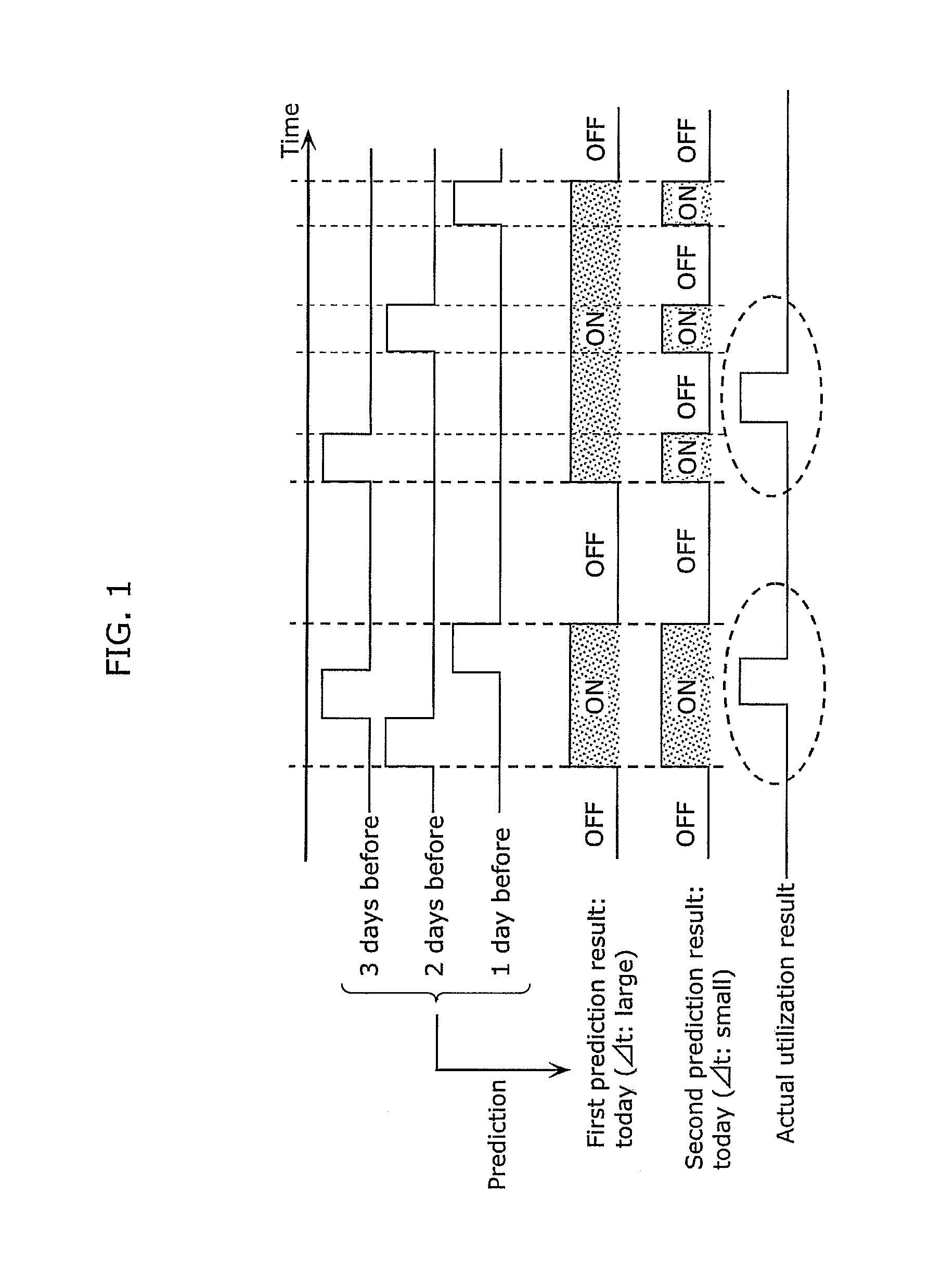
[0096]As described above, in the case where power supply is controlled for an appliance based on a prediction scheme using the past utilization history, there is a trade-off relationship between the power saving effect and the user load. The example will be specifically described with reference to FIG. 1.
[0097]FIG. 1 is a diagram for explaining a relationship between the user load and the power saving effect. In FIG. 1, an example will be shown whe...
embodiment 2
[0263]Next, Embodiment 2 will be described.
[0264]In the above Embodiment 1, the prediction interval prediction unit 106 uses the utilization history of the target appliance so as to predict a prediction interval which is a time interval which is predicted to have a high possibility that the appliance is utilized. More specifically, the prediction interval prediction unit 106 predicts, as a prediction interval, a time interval around the start time of the past utilization interval of the target appliance. The first prediction scheme is a prediction scheme using a property that an appliance is utilized in a predetermined cycle. The prediction scheme using such periodicity is effective for an appliance in which daily utilization intervals are concentrated on the same time to some extent. In other words, the prediction scheme using the periodicity is effective for the case where the start time of the utilization interval of the appliance has periodicity. However, the prediction scheme u...
modification 6
of Embodiment 2
[0359]In the above Embodiment 2, the prediction interval prediction unit 106 calculates a probability with respect to the utilization interval of the first appliance in which the utilization interval of the second appliance starts within the predetermined time ΔT2 from the start time or the end time of the utilization interval of the first appliance. Then, the prediction interval prediction unit 106 determines that there is a start relationship between the first appliance and the second appliance in the case where the calculated probability is greater than the threshold value. In the case where the scheme is used, a probability value of the second appliance having a low utilization frequency is smaller than that of the second appliance having a high utilization frequency, and therefore there are many cases where it is determined that there is no start relationship.
[0360]For example, assume when the start relationship between the appliances is calculated based on the u...
PUM
 Abstract
Description
Claims
Application Information
 - R&D
- Intellectual Property
- Life Sciences
- Materials
- Tech Scout
- Unparalleled Data Quality
- Higher Quality Content
- 60% Fewer Hallucinations
Browse by: Latest US Patents, China's latest patents, Technical Efficacy Thesaurus, Application Domain, Technology Topic, Popular Technical Reports.
© 2025 PatSnap. All rights reserved.Legal|Privacy policy|Modern Slavery Act Transparency Statement|Sitemap|About US| Contact US: help@patsnap.com


