refrigerator
A refrigerated cabinet and cold storage technology, applied in the field of refrigerated cabinets, can solve the problems of longer freezing time of cold storage agent, increased power consumption of refrigerated cabinets, reduced heat transfer efficiency, etc., to improve convenience, reduce costs, save electricity, improve The effect of transfer efficiency
- Summary
- Abstract
- Description
- Claims
- Application Information
AI Technical Summary
Problems solved by technology
Method used
Image
Examples
no. 1 approach
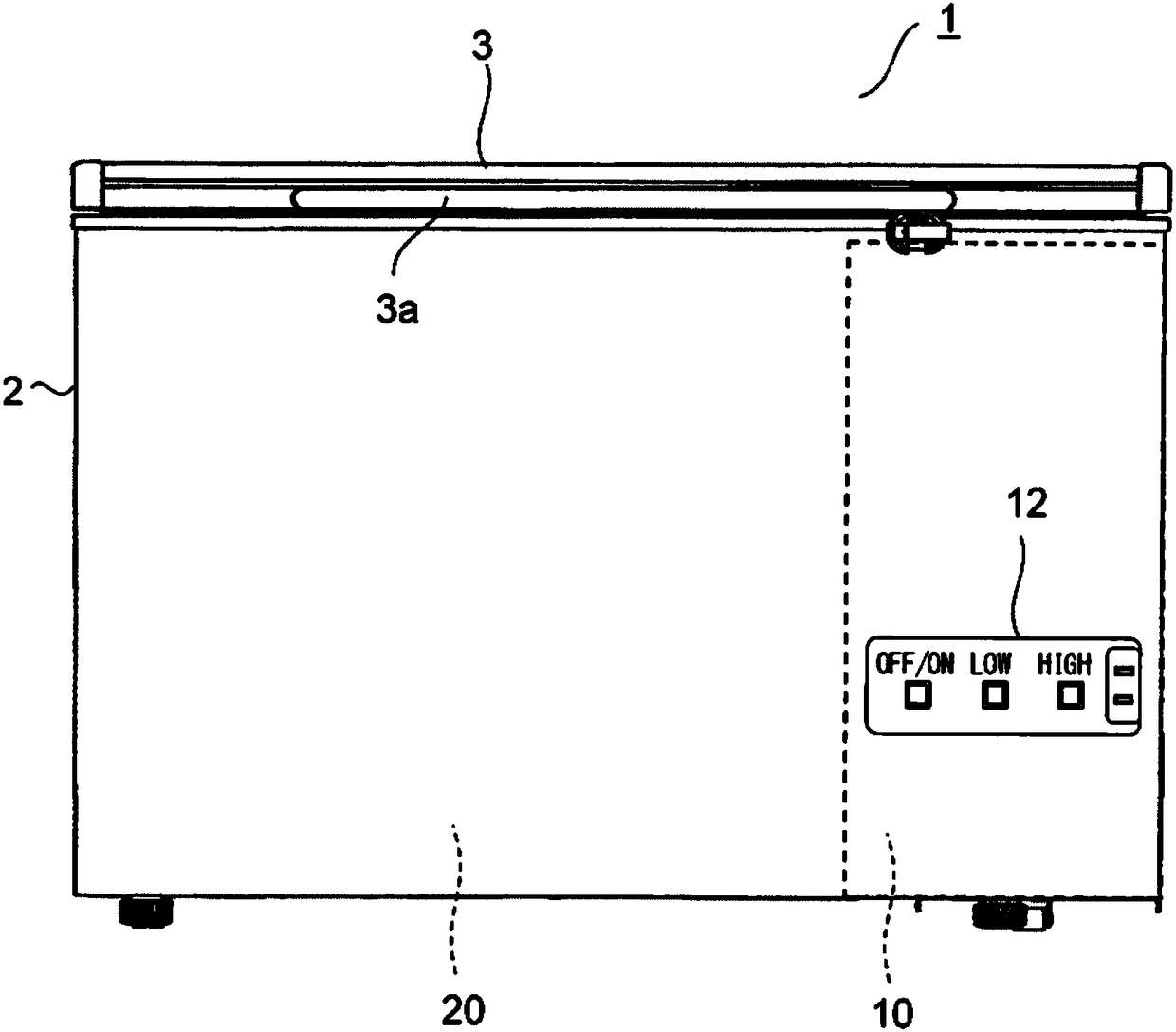
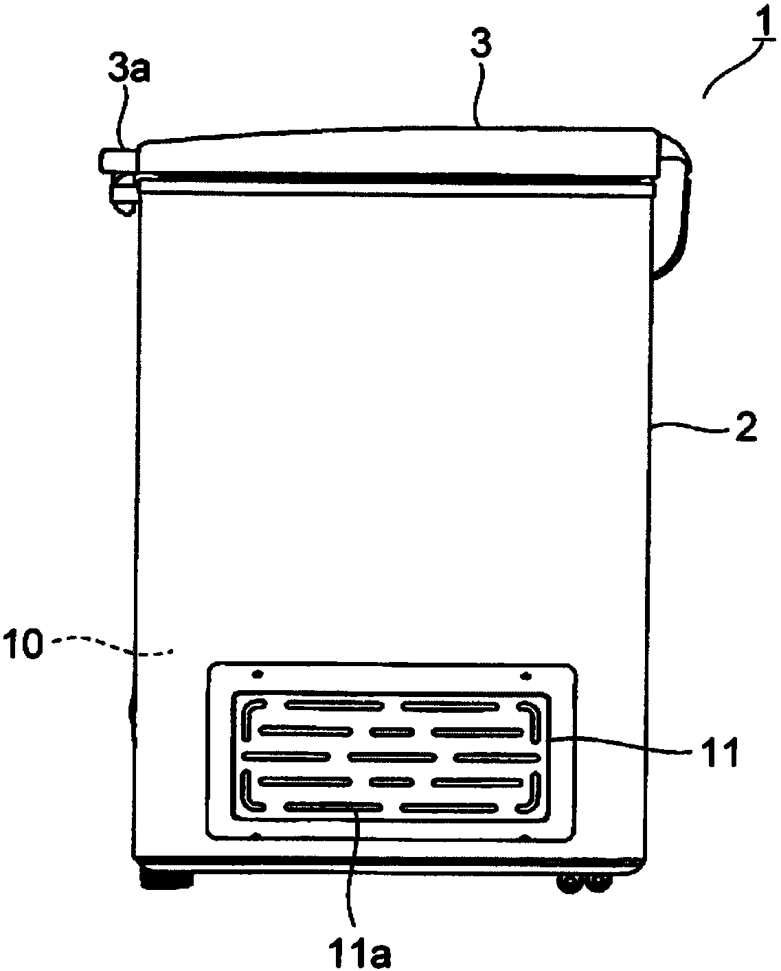
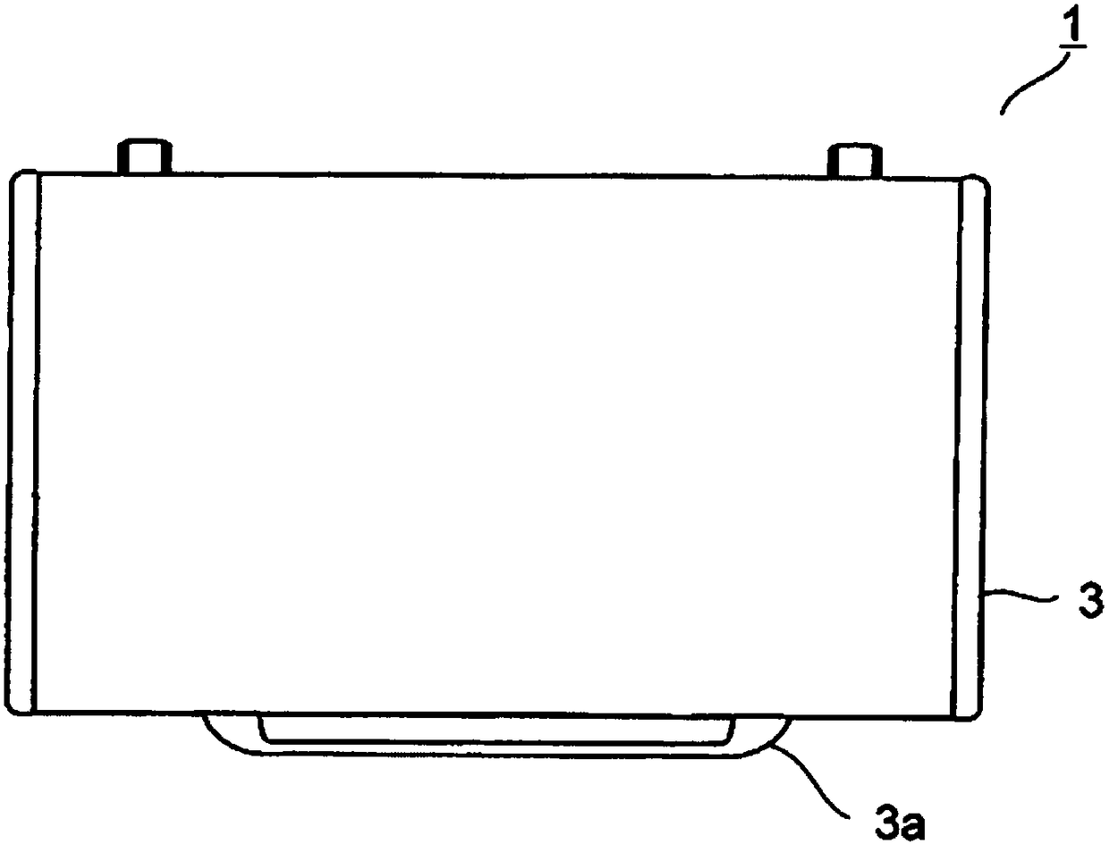
[0037] Hereinafter, embodiments of the present invention will be described with reference to the drawings. figure 1 , figure 2 and image 3 It is a front view, a side view, and a top view which show the refrigerator of 1st Embodiment. The refrigerator 1 includes: a main body 2 having a store room 20 with an open upper face; and an opening and closing door 3 (door) pivotally supported on the rear side of the main body 2 and opening and closing the upper face. The door 3 is opened and closed by holding the handle 3a provided on the front end.
[0038] A machine room 10 is provided at one end portion of the main body portion 2 . The machine room 10 has an opening (not shown) on the back and one side, and the opening is closed by a panel 11 having a vent hole 11a. A display panel 12 is provided on the front surface of the machine room 10 .
[0039] A lamp or the like is arranged on the display panel 12 , and the state of power supply to the refrigerator 1 and the temperature...
no. 2 approach
[0062] then, Figure 12 The front sectional view which shows the main-body part 2 of the refrigerator 1 which concerns on 2nd Embodiment. For the sake of illustration, with the Figure 1 to Figure 11 Like parts of the first embodiment shown are provided with the same reference numerals. In the present embodiment, cool storage bodies 30 are provided on two upper stages in store room 20 , and holding members 43 are provided between the cool storage bodies 30 on the upper and lower sides. Other parts are the same as the first embodiment.
[0063] The machine room 10 is provided at the lower part of one side end of the main body 2 , and the storage room 20 communicates with the side and the top of the machine room 10 . In the lower part of the storage room 20 , three regenerators 30 are arranged side by side on the front and rear inner surfaces, and two regenerators 30 are arranged side by side on the left inner surface along the front and rear directions. Since the cooling pa...
no. 3 approach
[0072] then, Figure 14 The front sectional view which shows the main-body part 2 of the refrigerator 1 which concerns on 3rd Embodiment. also, Figure 15 An exploded perspective view showing cool storage body 30 and holding members 41 , 42 , and 43 arranged inside storage compartment 20 . For the sake of illustration, with the Figure 12 , Figure 13 Like parts of the second embodiment shown are provided with the same reference numerals. In the present embodiment, the holding member 43 arranged between the upper and lower cool storage bodies 30 is divided into a holding member 43a and a holding member 43b. Other parts are the same as the second embodiment. In addition, in Figure 15 In , illustration of the cool storage body 30 on the front side is abbreviate|omitted.
[0073] The holding member 43a and the holding member 43b are formed in the same shape as the holding member 42, and are arranged so that the vertical direction is reversed. The holding member 43a mount...
PUM
 Abstract
Description
Claims
Application Information
 - R&D
- Intellectual Property
- Life Sciences
- Materials
- Tech Scout
- Unparalleled Data Quality
- Higher Quality Content
- 60% Fewer Hallucinations
Browse by: Latest US Patents, China's latest patents, Technical Efficacy Thesaurus, Application Domain, Technology Topic, Popular Technical Reports.
© 2025 PatSnap. All rights reserved.Legal|Privacy policy|Modern Slavery Act Transparency Statement|Sitemap|About US| Contact US: help@patsnap.com


