
Recoil damping device for portable firearms

a damping device and portable technology, applied in the direction of weapons, butts, weapon components, etc., can solve the problems of lateral shifting in the rearward motion of the rifle, loss of the aiming line and the correct firearm placement by the shooter, and the system is constructively complicated, therefore productively expensive and relatively heavy, so as to reduce the number of components, the effect of being lightweight and economical

Active Publication Date: 2015-05-05
BENELLI ARMI
View PDF33 Cites 1 Cited by
  • Summary
  • Abstract
  • Description
  • Claims
  • Application Information

AI Technical Summary

Benefits of technology

The technical effect of this patent is to provide a damping device that is easy to make, uses a few components, and is lightweight and cost-effective.

Problems solved by technology

An important drawback of that type of system is that the elastic portion deforms, during the recoil step, and easily causes lateral shifting in the rearward motion of the rifle.
Therefore, the motion of the recoiling firearm does not follow the longitudinal axis thereof but is diverted, with consequent loss of the aiming line and of the correct firearm placement by the shooter.
However, such system is constructively complicated and therefore productively expensive and relatively heavy.
The system described in U.S. Pat. No. 7,926,216 is constructively complicated and heavy.
In general, the above described prior art systems, based on mechanisms that are internal to the stock, have the drawback of being structurally complicated and therefore expensive.
The accessories to be applied to the stock can have a lower cost but do not offer optimal functional characteristics.
In practice, the system works well only for certain munitions but is far less effective for more powerful or weaker munitions.
In other words, in the case of much more powerful munitions, the traditional damper deforms excessively and fully collapses, transmitting a considerable impact force to the shooter's shoulder.
In the case of much weaker munitions, instead, the system does not deform sufficiently and does not reduce the effects of recoil.

Method used


Image

  • Recoil damping device for portable firearms
  • Recoil damping device for portable firearms
  • Recoil damping device for portable firearms

Examples


Embodiment Construction

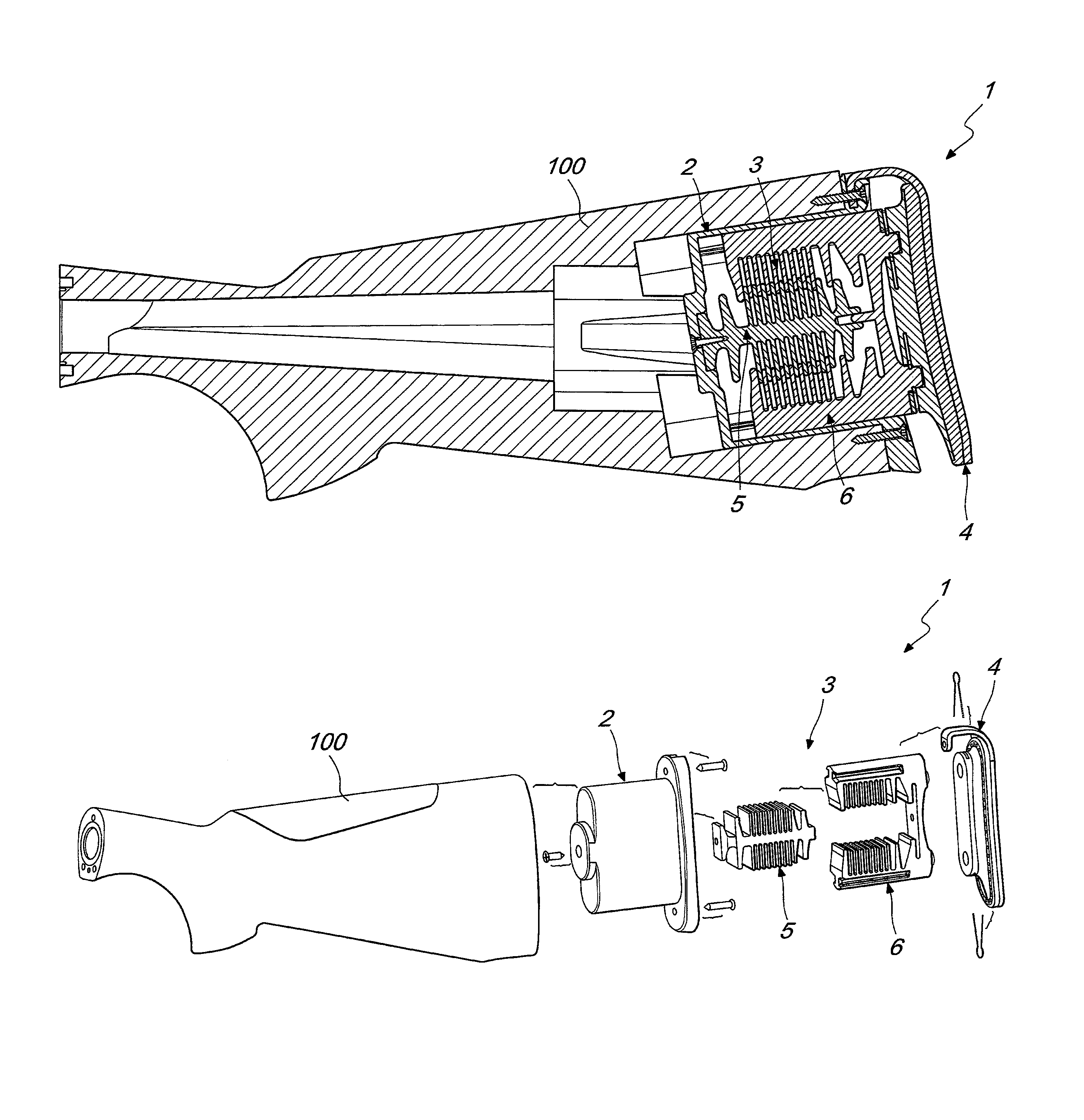
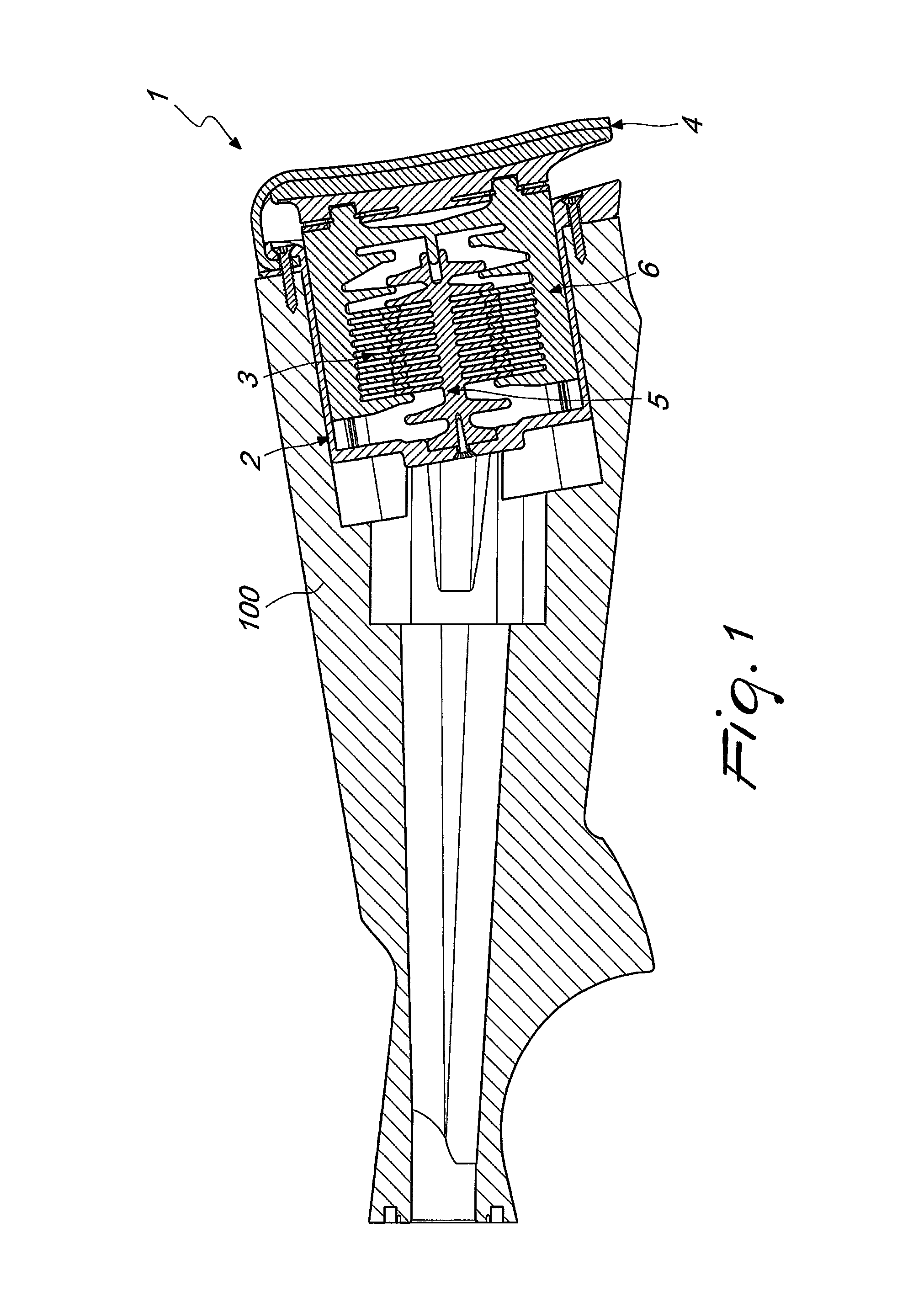
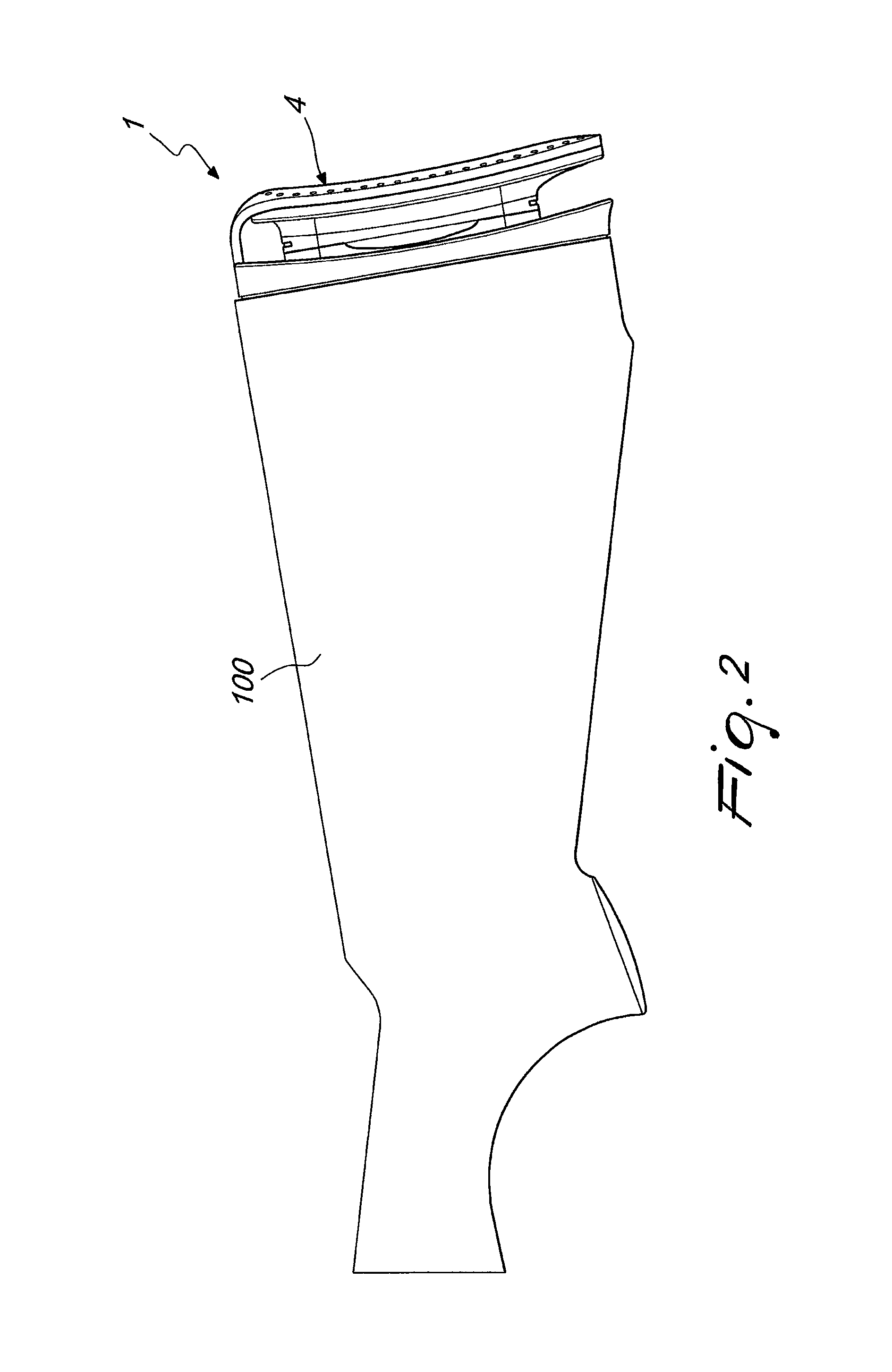
[0036]With reference to the cited figures, the device according to the invention, generally designated by the reference numeral 1, is arranged in a stock 100 of a firearm, such as, for example, a rifle.

[0037]The device 1 has a casing 2 that has a substantially oval cross-section and in which a damping means 3 is inserted.

[0038]The casing 2 can be an independent member, as in the illustrated example, or can be constituted by a seat provided in the stock of the firearm.

[0039]The device 1 includes furthermore a butt plate 4, which is functionally associated with the damping means 3 and is arranged outside the casing 2 and the stock 100.

[0040]The damping means 3 has a fixed part 5 and a movable part 6.

[0041]The fixed part 5 is substantially integral with the casing 2, and therefore with the stock 100 of the firearm, while the movable part 6 slides, along a substantially axial direction, within the casing 2.

[0042]The butt plate 4 is integral with the movable part 6 and therefore is movab...


PUM


Abstract

A recoil damping device for portable firearms, including a casing in which a recoil damping means is inserted; the damping means includes a fixed part, which is integral with the casing, and a movable part able to slide along a substantially axial direction inside the casing; the damping means is made of a material having a certain elastic hysteresis and includes a set of flexible members connecting the fixed part to the movable part; the flexible members have different stiffnesses.

Description

BACKGROUND OF THE INVENTION[0001]The present invention relates to a recoil damping device for portable firearms.[0002]As is known, the stock of rifles has the purpose of fixing the distance between the shooter's shoulder and the trigger, of taking part in defining the center of gravity of the firearm and of distributing the pressure generated by the recoil force over a larger surface, so as to reduce the unit value and transmit it to the shooter's shoulder.[0003]In order to reduce the dynamic load on the shoulder, caused by the recoil of the firearm, or to improve its ballistic characteristics, numerous devices have been proposed, including accessories to be applied to the stock and internal mechanisms of various kinds.[0004]Damping systems are known, for example, that are constituted by an elastic portion formed in the rear part of the stock and adapted to partially absorb the recoil energy by deforming.[0005]An important drawback of that type of system is that the elastic portion ...

Claims


Application Information

Patent Timeline
Patent Type & Authority Patents(United States)
IPC IPC(8): F41C23/06F41C23/08F41C23/18
CPCF41C23/06F41C23/18F41C23/08
Inventor MORETTI, LUIGI
Owner BENELLI ARMI
Learn More