
System for measuring suspension sag

a suspension and suspension technology, applied in the direction of mechanical measuring arrangements, instruments, mechanical means, etc., can solve the problems of inaccurate measurement, user error in reading the gradation, and inability to administer the practi

Active Publication Date: 2015-05-05
MOTOOL LLC
View PDF19 Cites 1 Cited by
  • Summary
  • Abstract
  • Description
  • Claims
  • Application Information

AI Technical Summary

Benefits of technology

The patent describes a system that measures the change in distance between two parts of a vehicle when a load is placed on it. It includes a measuring device and a clamp. The measuring device attaches to one part of the vehicle and has a mechanism that extends and retracts a cord. It also includes a rotary encoder that measures the rotation of this mechanism and converts it to a linear movement of the cord. The clamp attaches to the other part of the vehicle and receives the cord. By measuring the change in distance between the two parts, the system can identify the location of the load and help with load distribution and stability.

Problems solved by technology

However, when an assistant who can take this measurement is not available, this practice cannot be administered.
This movement shifts the operator out of a normal riding position and results in an inaccurate measurement because of the shifted weight.
This system, however, suffers from a number of drawbacks such as general difficulty in using, inaccuracy due to the sliding element or measuring ring moving beyond its position after the operator dismounts the vehicle, user error in reading the gradation or in calculating the measured distances and the inability to check instantaneous sag while the operator is mounted on the vehicle.

Method used


Image

  • System for measuring suspension sag
  • System for measuring suspension sag
  • System for measuring suspension sag

Examples


Embodiment Construction

[0014]As used herein, the term “sprung mass” is the mass of the vehicle's body and other components supported by the suspension, including the mass of the rider while mounted on the vehicle. The term “unsprung mass” includes the mass of components not supported by the suspension, such as for example, axles, hubs and tires.

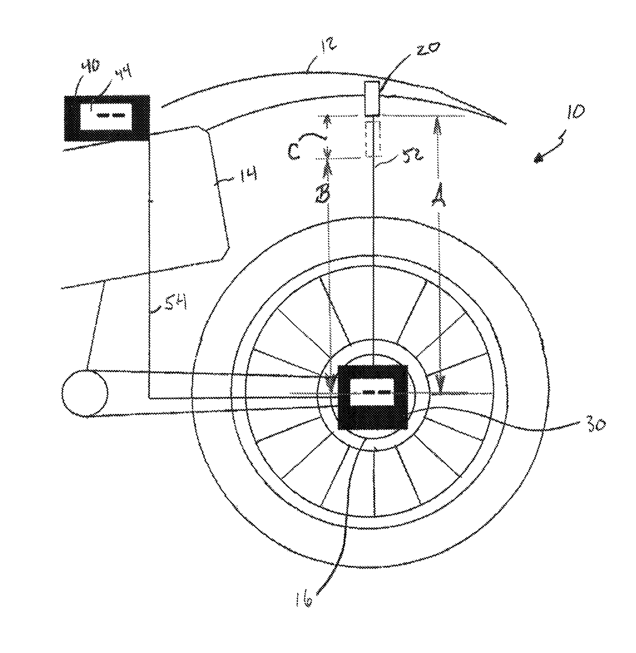
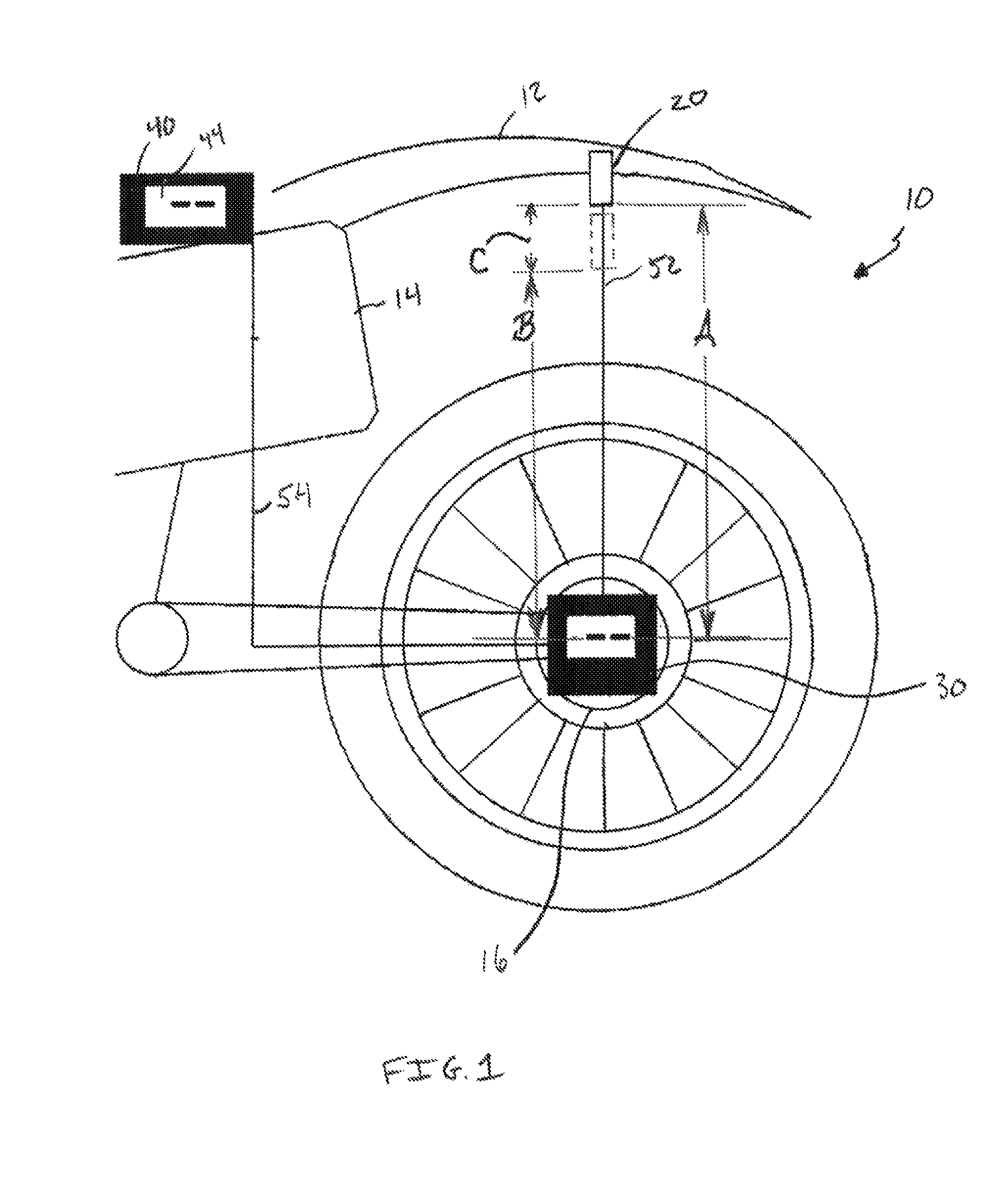
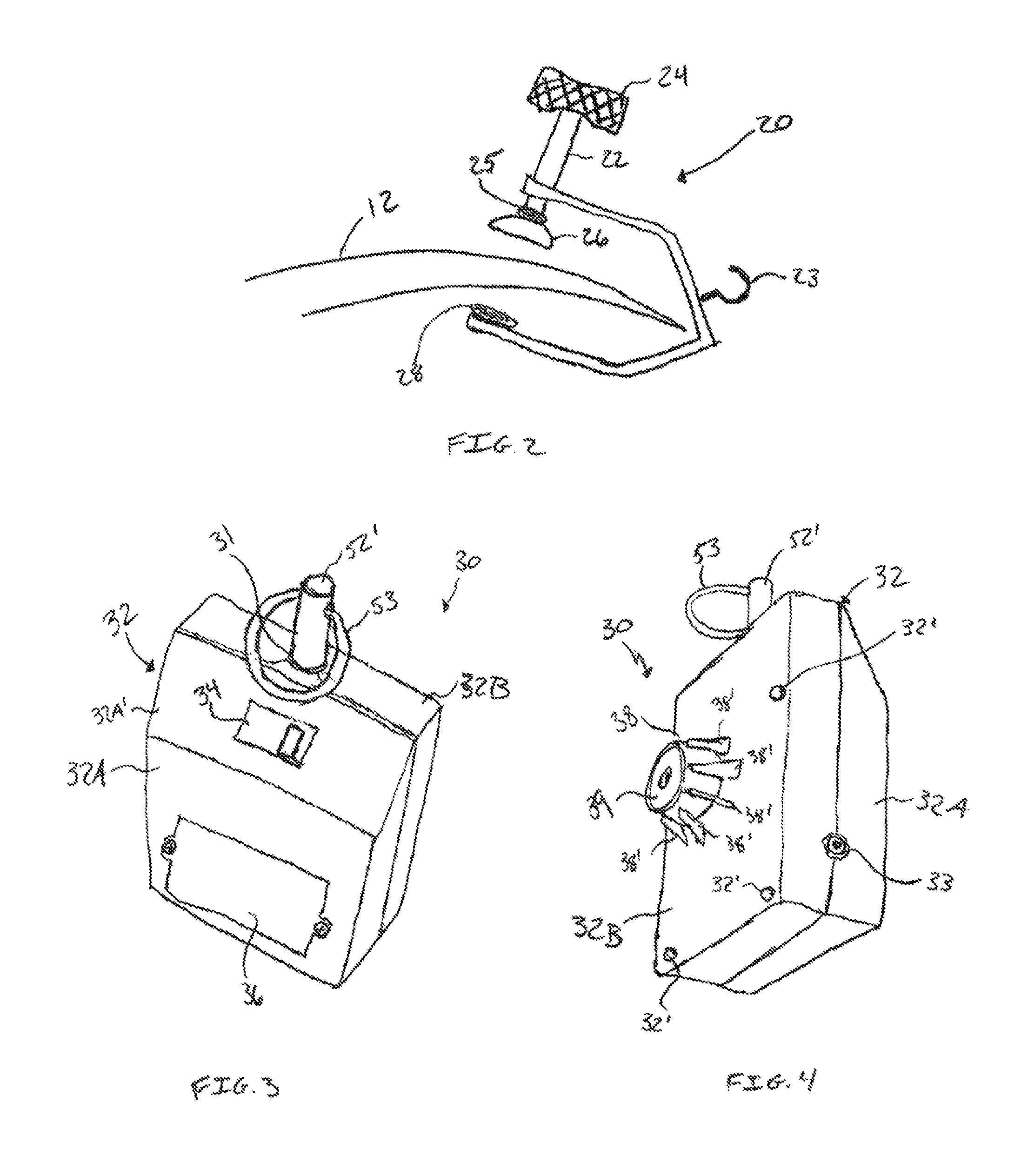
[0015]Referring to FIG. 1, by way of example, the embodiment of the present invention comprises a system 10 for measuring suspension sag. The system 10 may include a clamp 20, a measuring device 30, and an optional display unit 40. The system may also include a cord 52, which may connect the measuring device 30 to the clamp 20, and an optional cable 54, which may connect the measuring device 30 to the optional display unit 40. The clamp 20 may connect to a fender 12 of a vehicle 14, such as a motorcycle, or any other component of a vehicle's body. Measuring device 30 may be mounted to a hub 16 of the front or rear wheel of the vehicle.

[0016]Referring to FIG. 2, the...


PUM


Abstract

A system for measuring suspension sag in a vehicle, such as a motorcycle, is disclosed. The system includes a measuring device that attaches to a wheel hub, axle, or other component. The system includes a clamp that attaches to a fender or other vehicle component. The device is connected to the clamp by a cord, which extends from and retracts into the device. When a load is placed on the vehicle, the fender may move closer to the hub or axle. Any slack in the cord may be taken up by a spool shaft in the device. A rotary encoder may measure the rotation of the spool shaft, and the measuring device may calculate a change in a linear distance between, for example, the fender and the axle based on the rotation of the spool shaft.

Description

CROSS-REFERENCE TO RELATED APPLICATION[0001]This application claims the benefit of U.S. Provisional Patent Application No. 61 / 840,454, filed Jun. 27, 2013, which is hereby incorporated by reference in its entirety.TECHNICAL FIELD[0002]The present invention relates generally to devices and systems for measuring the sag of a motor vehicle suspension, e.g., on a motorcycle; more particularly to devices and systems used for measuring suspension sag that can be operated without the aid of an assistant; and most particularly to devices and systems for measuring the sag of a suspension that can be operated by a single individual while the individual maintains a proper riding position during measurement.BACKGROUND OF THE INVENTION[0003]When setting or calibrating the suspension of a vehicle, such as a motorcycle or all-terrain vehicle, it is most desirable to measure the amount the front and rear suspension sags while the operator is mounted on the vehicle in a normal seated position. This ...

Claims


Application Information

Patent Timeline
Patent Type & Authority Patents(United States)
IPC IPC(8): G01M17/04
CPCG01M17/04G01B3/11G01B5/0025G01B5/14G01B7/026
Inventor CASEBEER, II, JOHN CHARLES
Owner MOTOOL LLC
Learn More