Image reading apparatus

a reading apparatus and reading device technology, applied in the direction of electrographic process apparatus, instruments, corona discharge, etc., can solve the problems of stress concentration on broken wires in the harness, and the portion of the harness gets strewn, so as to reduce the stress concentration of the harness and increase the size of the reading apparatus

Active Publication Date: 2015-05-05
BROTHER KOGYO KK
View PDF22 Cites 1 Cited by
  • Summary
  • Abstract
  • Description
  • Claims
  • Application Information

AI Technical Summary

Benefits of technology

[0009]However, the bending (flexing) and straitening (stretching) of the harness are repeated above the retaining shaft in accordance with the opening and closing of the document cover, causing stress concentration on the portion of the harness which is bent along the upper portion of the retaining shaft. That is, the portion of the harness gets fatigued easily, leading to a broken wire in the harness. If a degree of bending of the bent portion of the harness is made larger, the stress concentration of the harness can be reduced, but the size of the image reading apparatus is increased.
[0010]This invention has been developed to provide an image reading apparatus capable of reducing stress concentration of a harness caused by opening and closing of a cover without increase in size of the image reading apparatus.

Problems solved by technology

However, the bending (flexing) and straitening (stretching) of the harness are repeated above the retaining shaft in accordance with the opening and closing of the document cover, causing stress concentration on the portion of the harness which is bent along the upper portion of the retaining shaft.
That is, the portion of the harness gets fatigued easily, leading to a broken wire in the harness.

Method used


Image

  • Image reading apparatus
  • Image reading apparatus
  • Image reading apparatus

Examples


Embodiment Construction

[0029]Hereinafter, there will be described one embodiment of the present invention by reference to the drawings.

[0030]

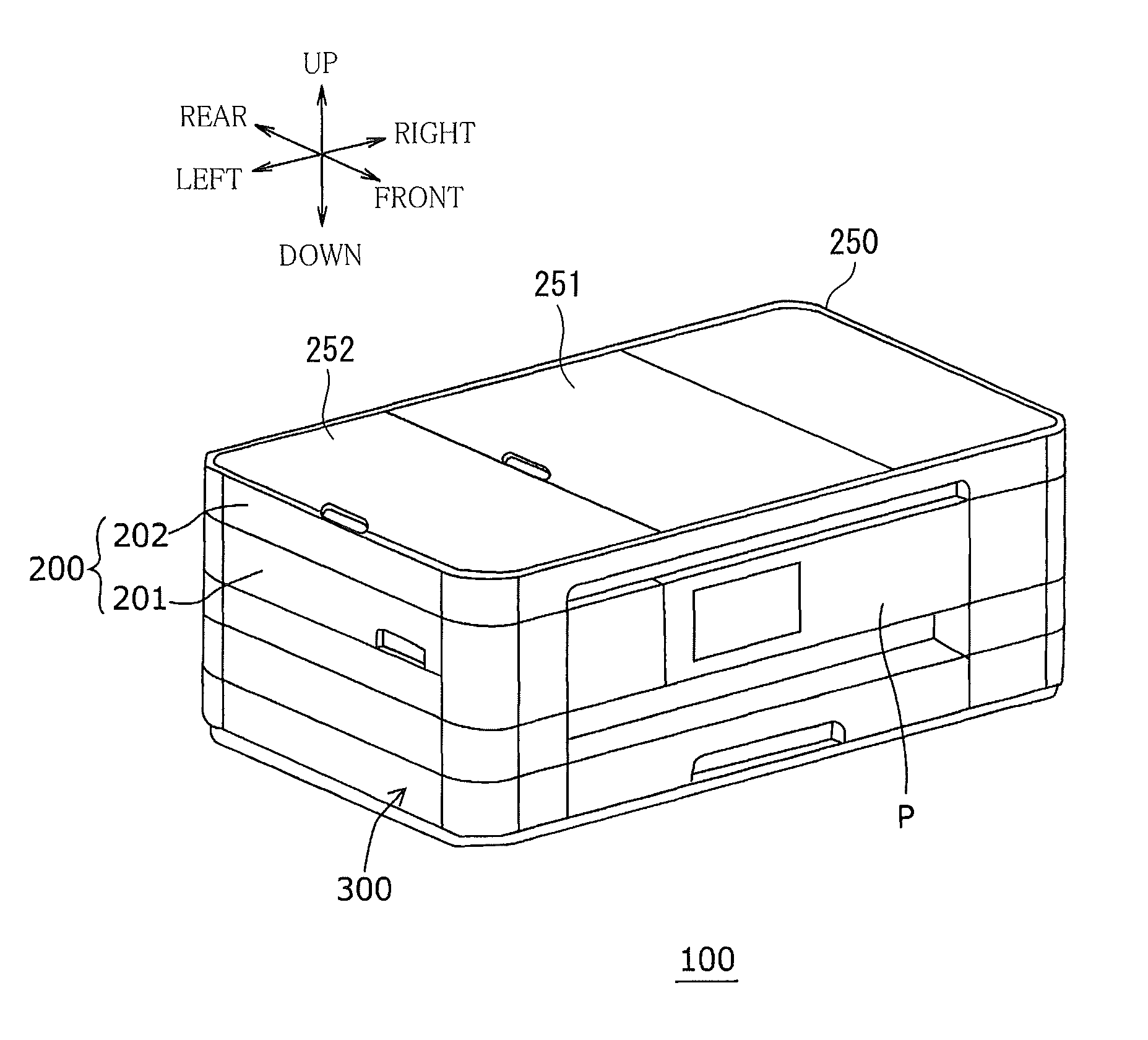
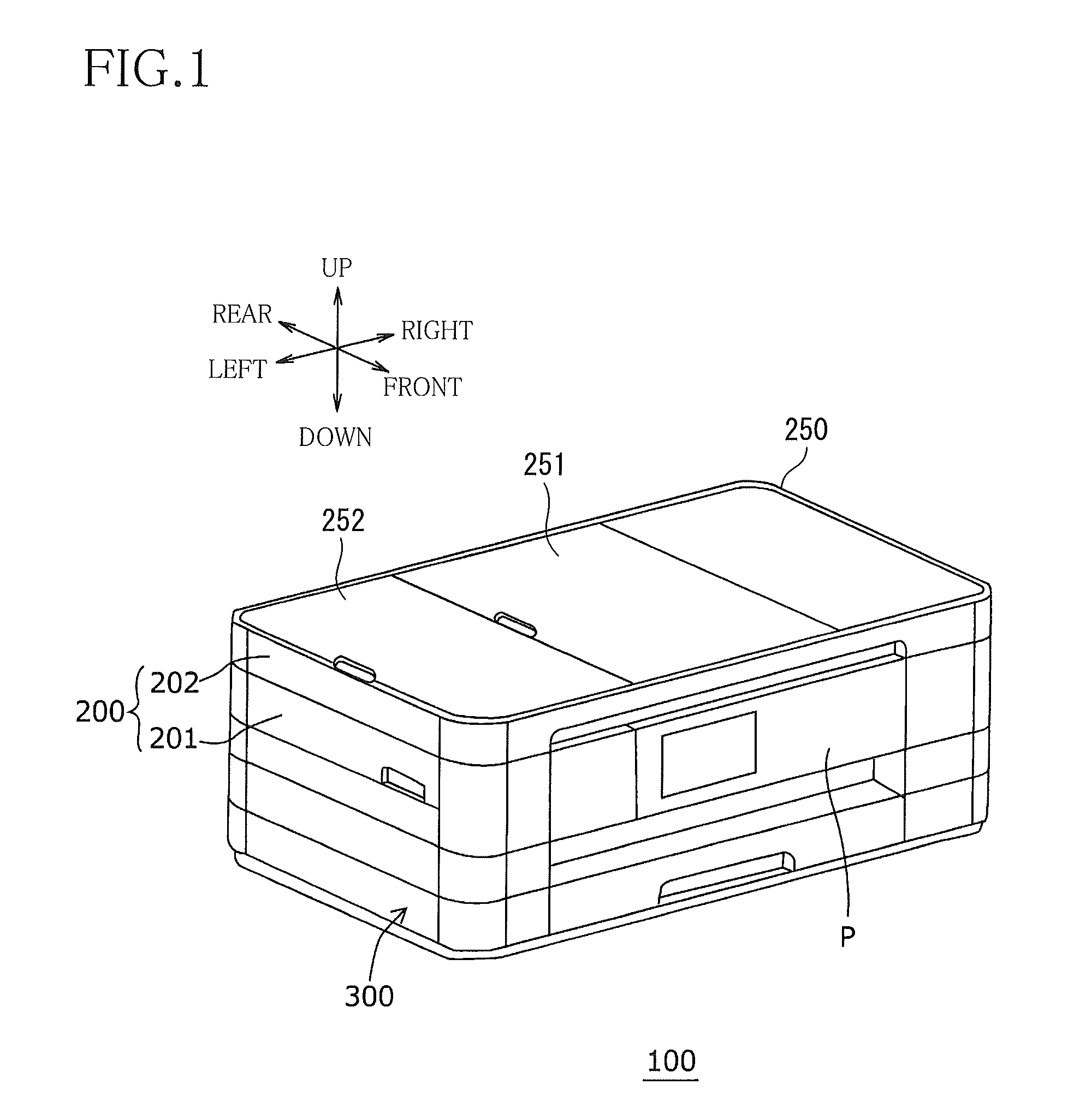
[0031]As illustrated in FIG. 1, an MFP 100 has a generally rectangular parallelepiped shape. The MFP 100 includes an image reading device 200 as one example of an image reading apparatus, and an image forming device 300 disposed under the image reading device 200.

[0032]It is noted that in a state in which the MFP 100 is placed on a horizontal surface, lengthwise directions of the MFP 100 in plan view are defined as right and left directions. Also, directions perpendicular to up and down directions and the lengthwise directions of the MFP 100 in plan view are defined as front and rear directions. Each direction is indicated by an arrow in each figure.

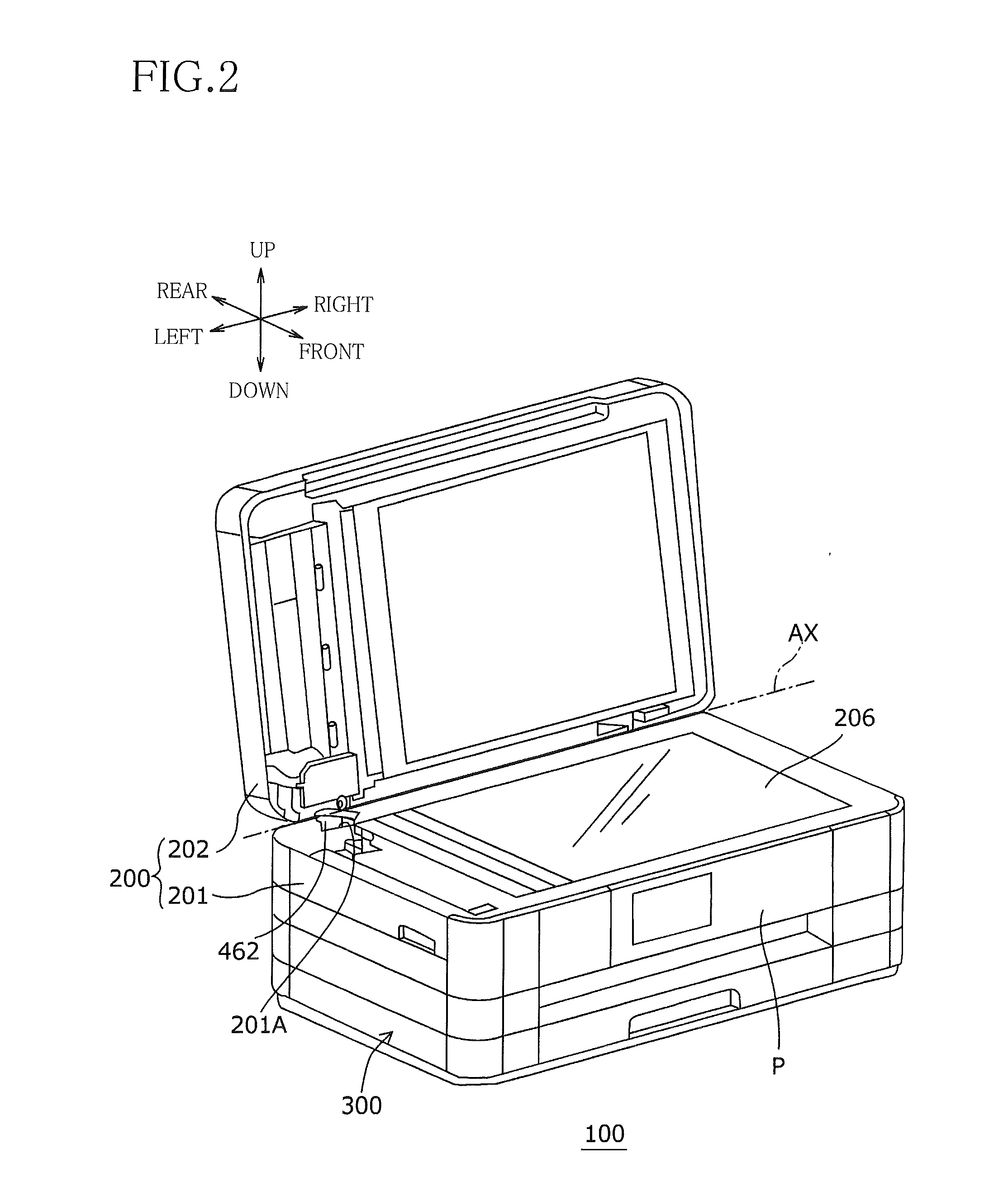
[0033]The image reading device 200 has a generally rectangular parallelepiped flat shape. The image reading device 200 includes an image reading main body 201 as one example of a housing, and an auto document feeder (ADF)...


PUM


Abstract

An image reading apparatus includes: a housing; a cover pivotable with respect to the housing about a first pivot axis extending in first directions that are opposite each other; a first electric component provided in the housing; a second electric component provided in the cover; and an electric wire configured to connect the first electric component and the second electric component to each other. The electric wire includes: a first extending portion retained by the cover and extending in the first directions; and a second extending portion movable relative to the cover and extending from the first extending portion toward the housing.

Description

CROSS REFERENCE TO RELATED APPLICATION[0001]The present application claims priority from Japanese Patent Application No. 2012-153071, which was filed on Jul. 6, 2012, the disclosure of which is herein incorporated by reference in its entirety.BACKGROUND OF THE INVENTION[0002]1. Field of the Invention[0003]The present invention relates to an image reading apparatus configured to read an image formed on a document.[0004]2. Description of the Related Art[0005]There is known an image reading apparatus including a main body and a document cover that is openable and closable with respect to the main body. A contact glass is disposed on an upper face of the main body. A reading unit is provided under the contact glass. The document cover is pivotable about a pivot axis to expose or cover an upper face of the contact glass.[0006]After the document cover is opened, a document is placed on the contact glass, and the document cover is closed. In this state, the contact glass is covered with th...

Claims


Application Information

Patent Timeline
Patent Type & Authority Patents(United States)
IPC IPC(8): H04N1/04H04N1/00
CPCH04N1/00559H04N1/00551H04N1/0083
Inventor MIURA, KATSURONISHIKAWA, YASUONANIWA, TAKUYA
Owner BROTHER KOGYO KK
Why Eureka
Try Eureka