Spring clamp

a spring clamp and spring technology, applied in the field of mechanical tools, can solve the problems of reducing the reliability of the spring clamp, easy overwear, and wasting the entire spring clamp

Inactive Publication Date: 2015-05-12
HANGZHOU GREAT STAR IND CO LTD +1
View PDF18 Cites 8 Cited by
  • Summary
  • Abstract
  • Description
  • Claims
  • Application Information

AI Technical Summary

Benefits of technology

[0033]The concept, structure and technical effects of the invention are further described with drawings in order to make the object, features and effects of the present invention understood.
are further described with drawings in order to make the object, features and effects of the present invention understood.

Problems solved by technology

As the holding strip is thin, the contact area between the holding strip edges and edges of both edges of the opening is usually a point contact or short line contact, which is easily overly worn.
The reliability of its locking function will be gradually reduced in use, and the locking function will even become completely invalid when the wear reaches a certain extent, which make the entire spring clamp useless.
Though according to the improved technology in the U.S. Pat. No. 6,860,179B2, i.e. the holding strip edge and both edges the opening adopting round corner structure, excessive wear still can not be completely avoided.
Therefore, for such spring clamps, requirements for the material of the holding strip and the opening of the locking bar are high, which results in increased cost.
And also high requirements for machining for the size precision in longitudinal direction of the opening, which directly results in an increased cost.
As part of the L-shaped element projecting beyond the body, another hand is required to help the adjustment, which reduces the freedom of hands and the convenience in use.
And the friction surface of the rod-shaped object and the L-shaped element is substantially parallel to the pivot, in which the aforementioned excessive wear and the decrease of the reliability of the locking function over a long-term use also reside, causing high requirements for the material and increased manufacturing cost.

Method used


Image

  • Spring clamp
  • Spring clamp
  • Spring clamp

Examples


embodiment 1

The Embodiment 1

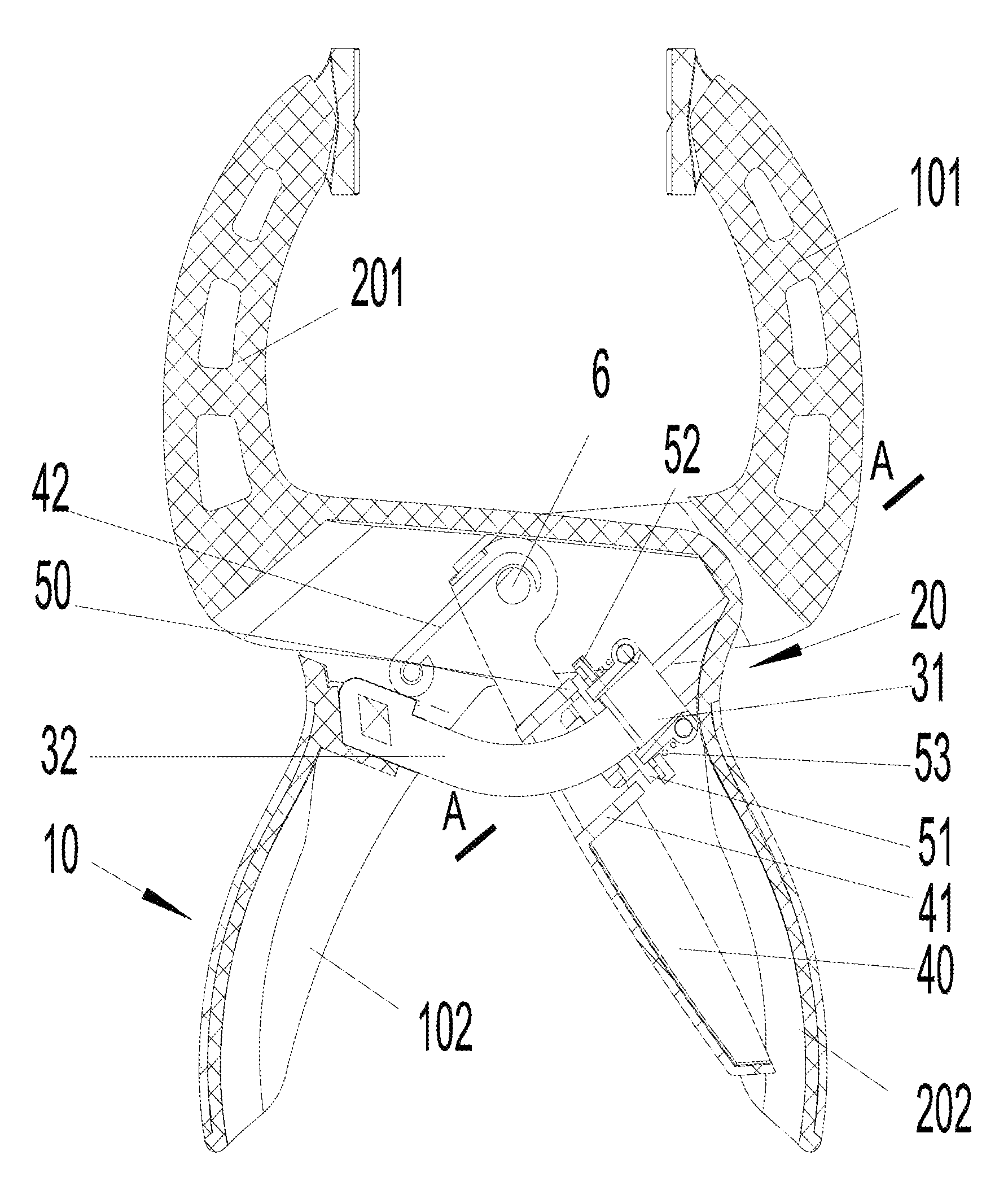
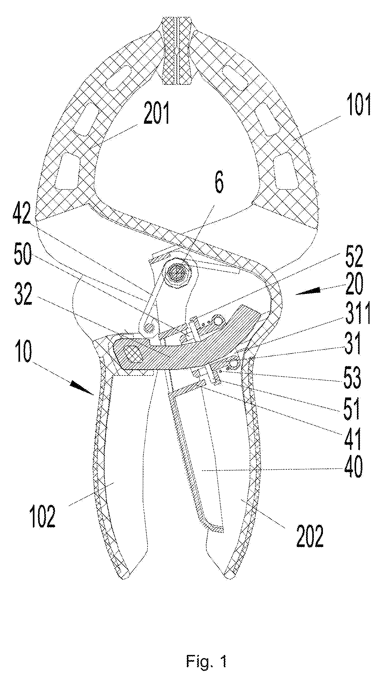
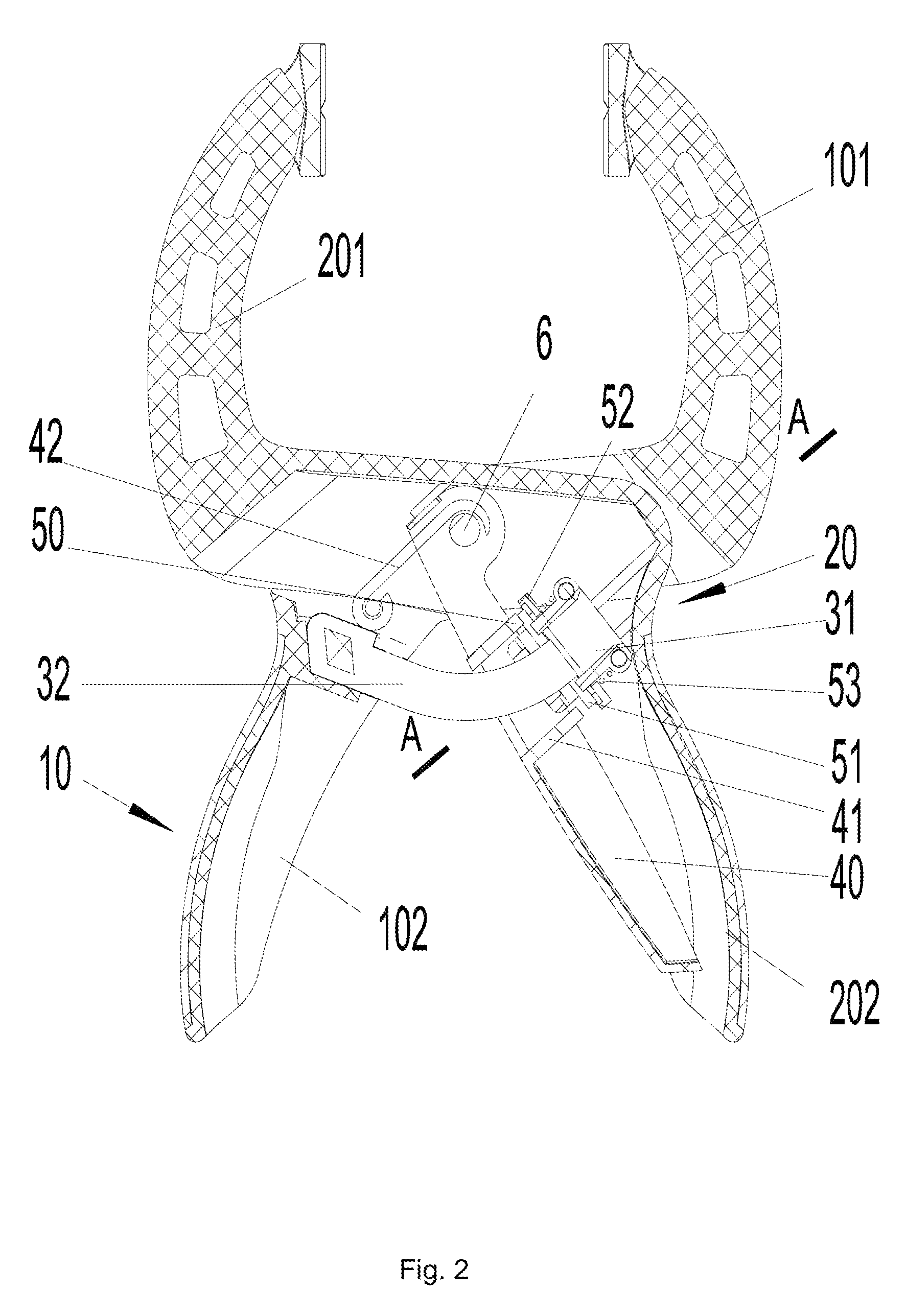
[0047]As shown in FIG. 1 and FIG. 2, the spring clamp in an embodiment of the present invention comprises a first body 10, a second body 20, and a first pivot 6 which pivotally connect the first body 10 and the second body 20. The first body 10 and the second body 20 have gripping portions 102, 202 and clamping portions 101, 201 respectively. The clamping portions of two bodies 10, 20 can be arranged with movable clamping heads respectively to facilitate clamping.

[0048]The First pivot 6 is made of screws, bolt, rivet, etc., and is located in middle of the first body 10 and the second body 20, and the lower halves of the first body 10 and the second body 20 can each form into a half-open cavity, respectively. Moreover, the outside thereof may be coated with soft coating layer, such as leather, artificial leather, plastic or rubber, etc.

[0049]Further, the spring clamp in this embodiment includes a locking mechanism which comprises a pair of friction pair components, an...

embodiment 2

The Embodiment 2

[0068]The structure of the spring clamp in another embodiment of the present invention is similar to that of the embodiment 1, while the difference is the locking mechanism. As shown in FIG. 4, there're two sets of strip hole 50 and 50′ provided in the clamp block 301 of the locking mechanism. There're two needles 51 and 51′ with two ends exposed out of the strip holes. Needle 51 and the free end 322 of the holding strip make up a set of pairs of friction pair elements while needle 51′ and the free end 322 of the holding strip make up another set of pairs of friction pair elements. The two sets of pairs of friction pair elements interact with each other to achieve the function of stepless locking of the spring clamp in the present embodiment.

[0069]The working principle of the present embodiment is the same as the embodiment 1, so it is not restated.

embodiment 3

The Embodiment 3

[0070]The structure of the spring clamp in another embodiment of the present invention is similar to that of the embodiment 1, the difference is that the second friction pair component of the locking mechanism is replaced by a new second friction pair component 131, which comprises clamp block 1301, wedge block 151, wedge block fixing ring 152 and elastic element 153 as shown in FIG. 5. The clamp block 1301 is provided with wedge block guide channel 150 on both sides, and the wedge block 151 in the wedge block guide channel 150 is provided, which has two ends exposed out of the wedge block guide channel 150. The wedge block 151 constitutes the second friction pair element. On the outside of the clamp block 1301 is provided an elastic element 153, and the wedge block 151 is pushed by a wedge block fixing ring 152 to move toward the direction close to the free end 322 of the holding strip along the wedge block guide channel 150. The wedge block fixing ring 152 also ser...


PUM


Abstract

A spring clamp includes a first body which comprises a gripping portion and a clamping portion, a second body which comprises a gripping portion and a clamping portion, a first pivot element which pivotally connects the first body and the second body, and a locking mechanism which comprises at least a pair of friction pair components. The first friction pair component is arranged on the first body, and includes a first friction pair element; and the second friction pair component is arranged on the second body, and includes a second friction pair element. The first and second friction pair elements rub against each other to effect the locking function. The rubbing of the friction pair elements occurs mainly in the plane perpendicular to the first pivot element axis.

Description

FIELD OF THE INVENTION[0001]The present invention relates to the field of mechanical tool and more particularly, to a spring clamp with stepless adjustment.DESCRIPTION OF THE PRIOR ART[0002]During the use of a spring clamp, the opening degree of the spring clamp nip is required to be adjusted according to the size of the clamped object. And the opening degree is preferred to be fixed in operation. In order to fix the adjusted opening degree, a large number of spring clamps with a locking mechanism has been known in the prior art.[0003]U.S. Pat. No. 6,708,587B1 has disclosed a spring clamps, which has the manipulating component arranged on an outside of the clamp handle and can be thumb-operated, which simplifies the labor by hand. But the technical solution of providing rack pairs on the clamp handle actualizes a step adjustment.[0004]The spring clamp disclosed in U.S. Pat. No. 6,860,179B2 and U.S. Pat. No. 7,406,897B2 has the manipulating component arranged on the inside of the cla...

Claims


Application Information

Patent Timeline
Patent Type & Authority Patents(United States)
IPC IPC(8): B25B3/00B25B5/04B25B5/06B25B5/16B25B7/06B25B7/14B25B7/16B25B25/00
CPCB25B5/04B25B5/06B25B7/14B25B7/16B25B7/06B25B25/00B25B5/163
Inventor LI, YUEMING
Owner HANGZHOU GREAT STAR IND CO LTD
Why Eureka
Try Eureka