

Airbag apparatus
- Summary
- Abstract
- Description
- Claims
- Application Information
AI Technical Summary
Benefits of technology
Problems solved by technology
Method used
Image

Examples
first exemplary embodiment
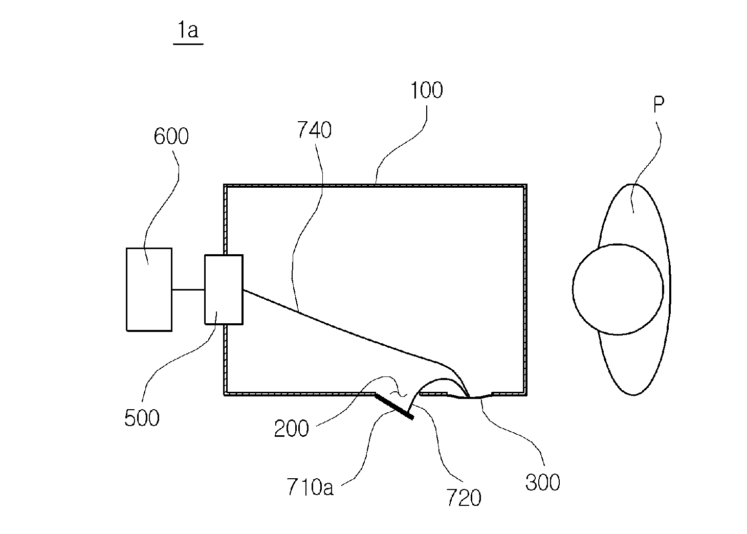
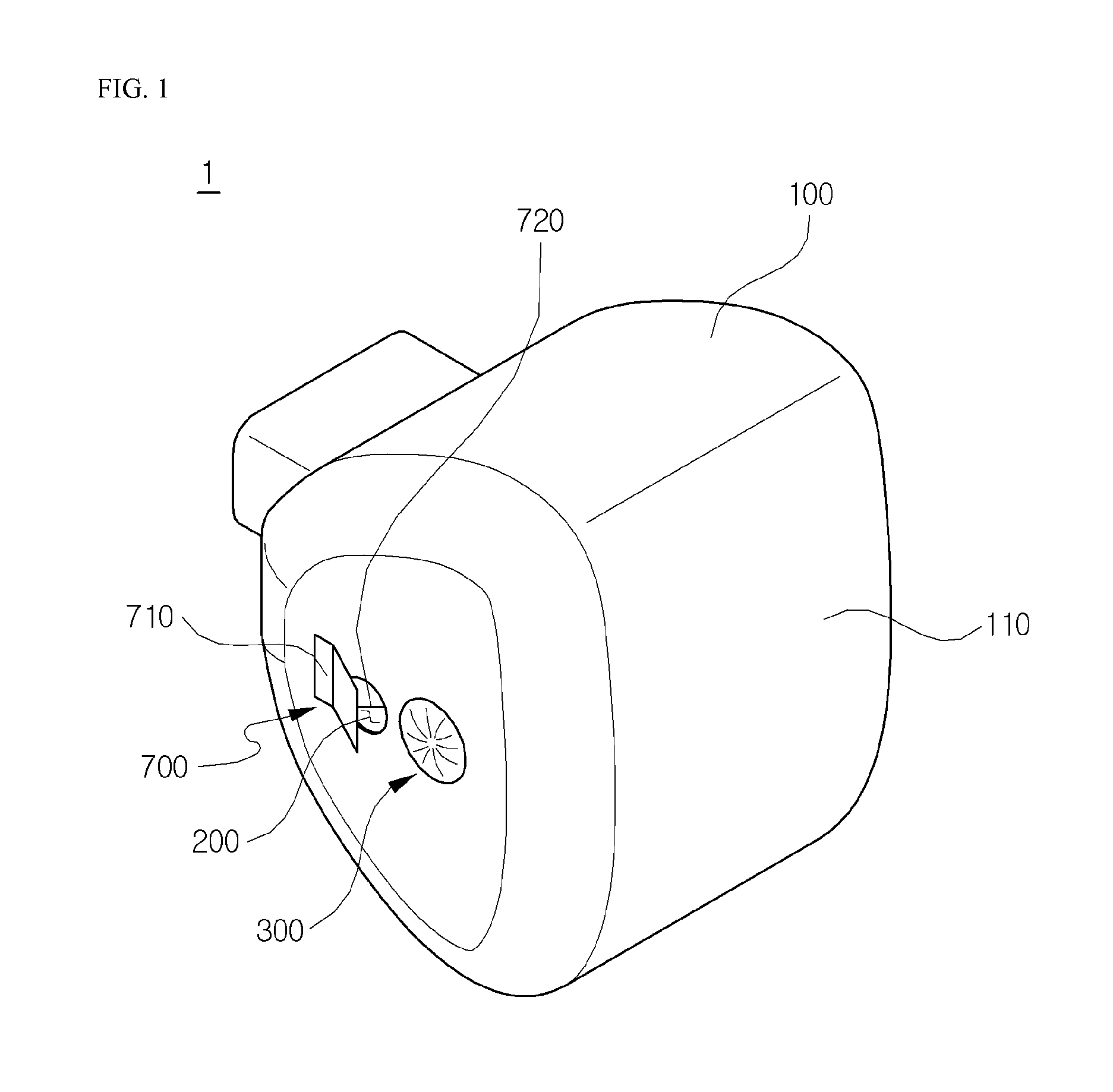
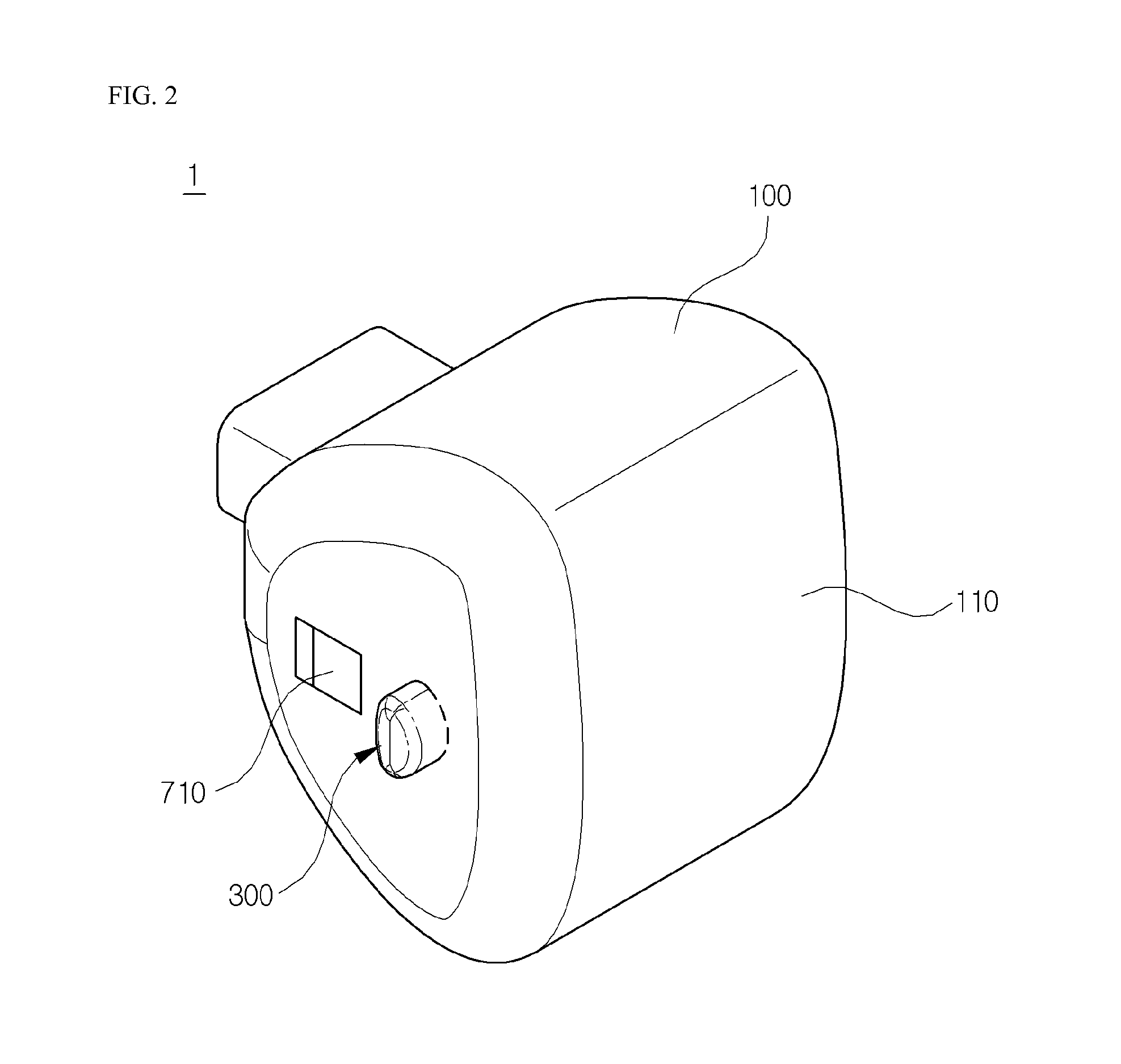
[0042]Referring to FIGS. 1 to 4, an airbag apparatus 1a according to an exemplary embodiment of the present invention may include an airbag main body 100, a vent 200, a pocket 300, a releasing unit 500, a control unit 600, a shield 700, and a tether 720.
[0043]The airbag main body 100 is deployed by gas generated by an inflator (not illustrated) at the time of a vehicle collision, and serves to mitigate impact to an occupant P who collides with the airbag main body 100.
[0044]The vent 200 and the pocket 300 may be provided at one side of the airbag main body 100.
[0045]As illustrated in FIGS. 1 and 3A, because the vent 200 is formed in the opened state, the vent 200 leaks the gas even during the deployment of the airbag main body 100 so as to prevent deployment pressure of the airbag main body 100 from being excessively increased.
[0046]Because the opened vent 200 leaks the gas flowing into the airbag main body 100 even when the occupant P collides with the airbag main body 100, the ope...
second exemplary embodiment
[0064]FIGS. 5A and 5B are views illustrating an airbag apparatus 1b according to another exemplary embodiment of the present invention.
[0065]Hereinafter, when the airbag apparatus 1b according to the second exemplary embodiment of the present invention is described, description of constituent elements identical to the constituent elements of the airbag apparatus 1a according to the first exemplary embodiment of the present invention will be omitted.
[0066]The airbag apparatus 1b may include an airbag main body 100, a vent 200, a pocket 300, a tether releasing unit 500, a control unit 600, a shield 700, and a tether 720.
[0067]The shield 700 shields the vent 200 while being operated in conjunction with the expansion of the pocket 300.
[0068]The shield 700 may include a tube 710b and the tether 720.
[0069]As illustrated in FIGS. 5A and 5B, the tube 710b is installed at one side of the airbag main body 100 so as to shield the vent 200.
[0070]The tube 710b has a pocket shape having an openin...
third exemplary embodiment
[0075]Referring to FIGS. 6A and 6B, an airbag apparatus 1c according to still another exemplary embodiment of the present invention may include an airbag main body 100, at least two vents 200, hinge portions 400, shields 700, and a tether 760. Here, the airbag main body 100 has a loading region 110 with which the occupant P collides, and the number of shields 700 corresponds to the number of vents 200 such that the shields 700 are installed to shield the vents 200, respectively.
[0076]The airbag main body 100 is deployed by gas generated by an inflator (not illustrated) at the time of a vehicle collision, and serves to mitigate impact to an occupant P who collides with the airbag main body 100.
[0077]At least two vents 200 may be provided at one side of the airbag main body 100.
[0078]As illustrated in FIG. 6A, because the vent 200 is formed in the opened state when the gas flows into the airbag main body 100, the vent 200 leaks the gas even during the deployment of the airbag main bod...
PUM
 Abstract
Description
Claims
Application Information