Power safety instrument system

a safety instrument and power technology, applied in the direction of navigation instruments, process and machine control, simultaneous indication of multiple variables, etc., can solve the problems of loss of rotor rpm, crash landing, uncontrolled descent,

Active Publication Date: 2015-05-19
TEXTRON INNOVATIONS
View PDF14 Cites 10 Cited by
  • Summary
  • Abstract
  • Description
  • Claims
  • Application Information

AI Technical Summary

Problems solved by technology

For example, as the rotorcraft is slowed to a landing, the increased power requirement at hover can consume all the power that the engine(s) have available (particularly with a heavy aircraft at a hot temperature and high altitude environment) causing loss of rotor rpm, an uncontrolled descent, and possibly a crash landing.
Each of these variables can be difficult to accurately predict.
There are many potential error opportunities due to the pilot having to read one or more charts, as well as make predictions regarding future flight conditions and atmospheric conditions.
Furthermore, pilots typically are very conservative in order to allocate margin for any calculation errors.
As a result, many rotorcraft are not fully utilized as pilots protect themselves and passengers from small but consequential errors and in-flight changes in the predicted variables (aircraft weight, outside air temperature, and pressure altitude).
Such underutilization of rotorcraft cost rotorcraft operators an enormous amount of time and money over the life of a rotorcraft.

Method used

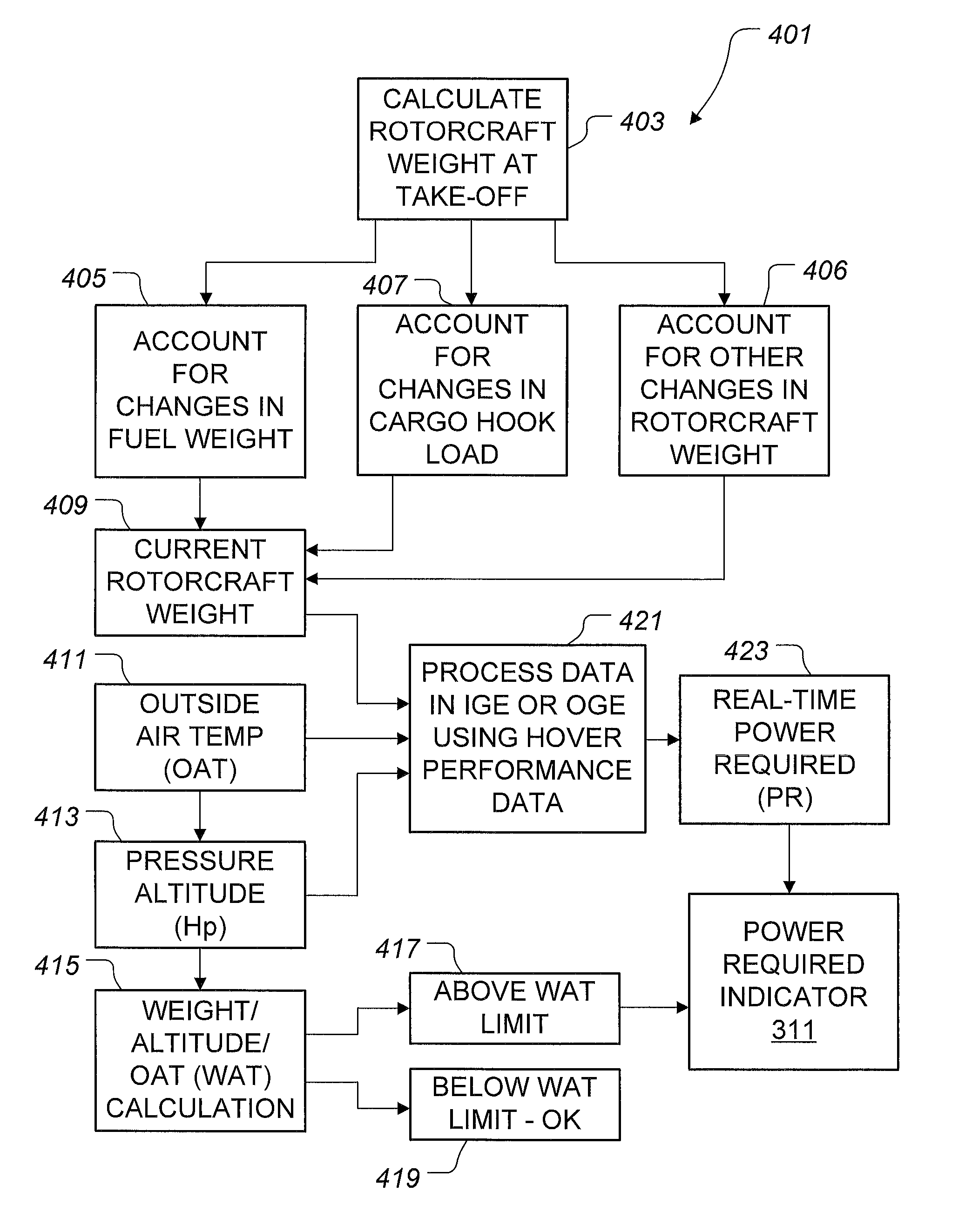
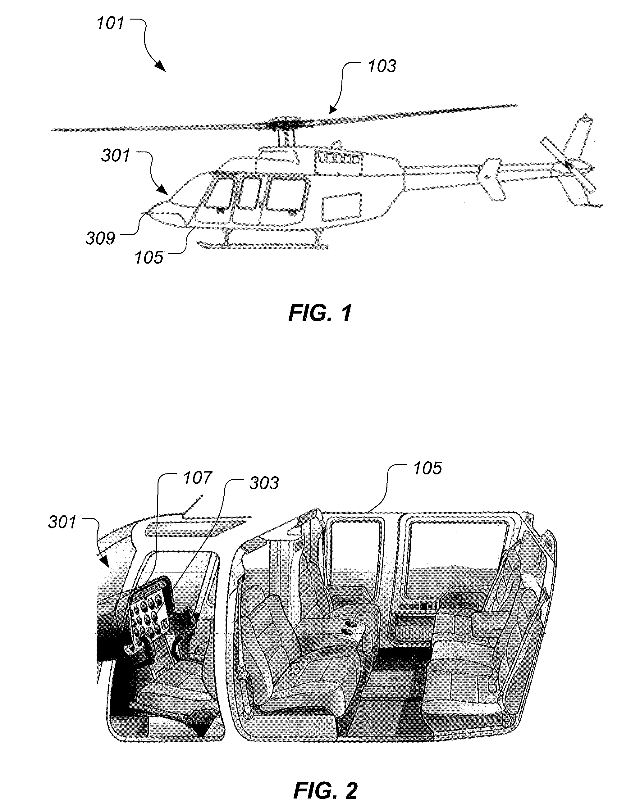
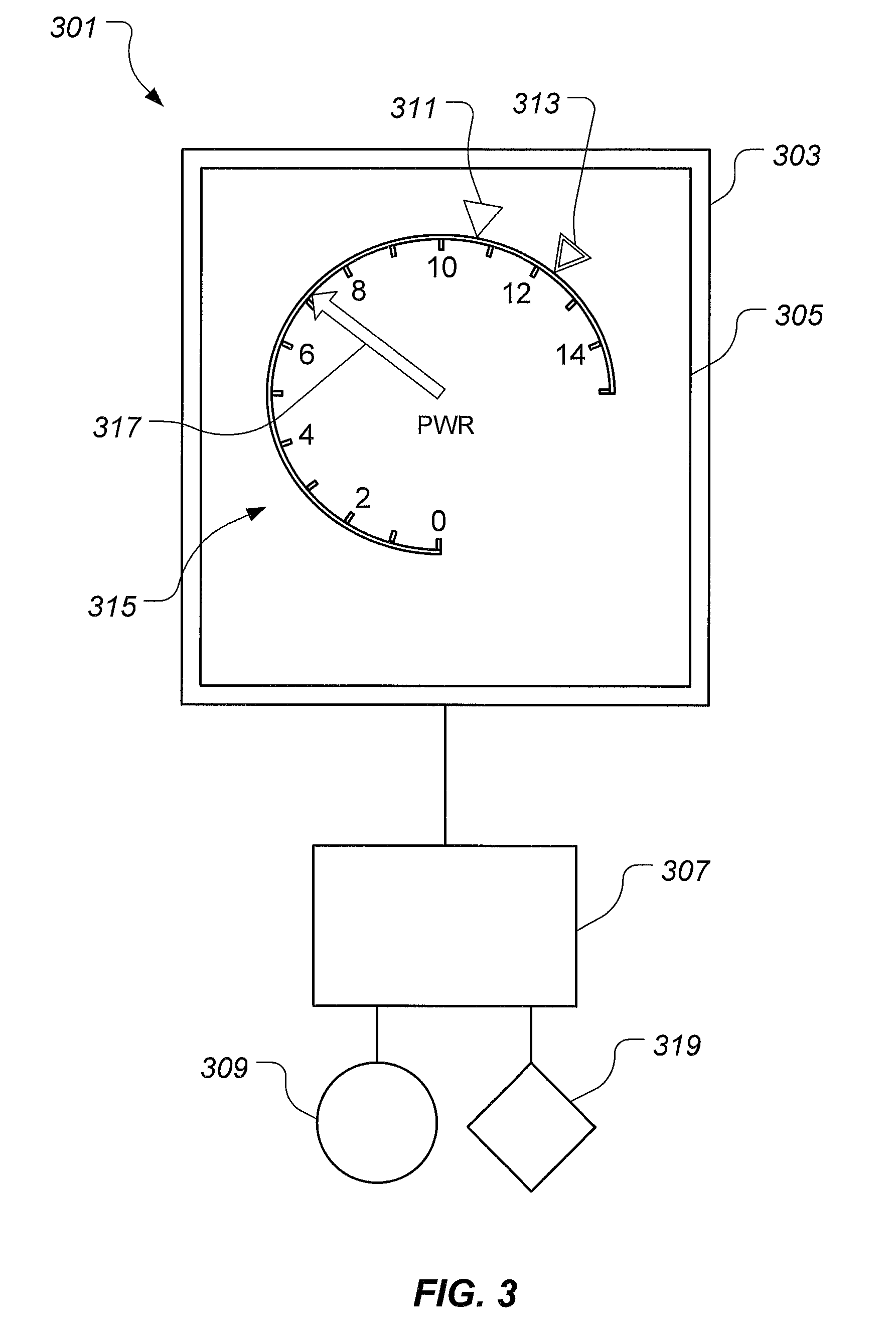

Image

  • Power safety instrument system
  • Power safety instrument system
  • Power safety instrument system

Examples


Embodiment Construction

[0015]Illustrative embodiments of the system of the present application are described below. In the interest of clarity, not all features of an actual implementation are described in this specification. It will of course be appreciated that in the development of any such actual embodiment, numerous implementation-specific decisions must be made to achieve the developer's specific goals, such as compliance with system-related and business-related constraints, which will vary from one implementation to another. Moreover, it will be appreciated that such a development effort might be complex and time-consuming but would nevertheless be a routine undertaking for those of ordinary skill in the art having the benefit of this disclosure.

[0016]In the specification, reference may be made to the spatial relationships between various components and to the spatial orientation of various aspects of components as the devices are depicted in the attached drawings. However, as will be recognized by...


PUM


Abstract

A power safety system is configured to provide power information in an aircraft. The power safety system includes a power safety instrument having a power required indicator and a power available indicator, each being located on a display. A position of the power required indicator and the power available indicator represent the power available and power required to perform a hover flight maneuver. The power safety system may be operated in a flight planning mode or in a current flight mode. The power safety system uses at least one sensor to measure variables having an effect on the power required and the power available.

Description

CROSS-REFERENCE TO RELATED APPLICATIONS[0001]U.S. Pat. No. 7,414,544 to Oltheten et al., is hereby incorporated by reference.TECHNICAL FIELD[0002]The system of the present application relates to a flight instrument for an aircraft. In particular, the system of the present application relates to a power safety instrument for a rotorcraft.DESCRIPTION OF THE PRIOR ART[0003]The power required to operate a rotorcraft may substantially change during the flight path of the rotorcraft. A rotorcraft typically requires substantially more power during a hover, compared to when the rotorcraft is traveling forward at a moderate airspeed. For example, as the rotorcraft is slowed to a landing, the increased power requirement at hover can consume all the power that the engine(s) have available (particularly with a heavy aircraft at a hot temperature and high altitude environment) causing loss of rotor rpm, an uncontrolled descent, and possibly a crash landing. Furthermore, the exact power required ...

Claims


Application Information

Patent Timeline
Patent Type & Authority Patents(United States)
IPC IPC(8): G08B21/00B60Q1/00B64C27/04B64D43/00
CPCB60Q1/00B64C27/04B64D43/00B64U30/20B64D45/00B64U2101/15B64C27/00B64C27/52B64C29/00B64C39/024B64C27/006G01C23/00G01D7/02G05D17/02B60C1/00
Inventor MCCOLLOUGH, JAMES M.OLTHETEN, ERIKLAPPOS, NICHOLAS
Owner TEXTRON INNOVATIONS
Why Eureka
Try Eureka