Switch signal output channel detection method and structure

A technology of digital output and channel detection, which is applied in the field of safety instrumented systems, can solve problems such as inability to disconnect output channels, on-site danger, failure to isolate faults, etc., and achieve the effect of improving fault handling capabilities and safety

Active Publication Date: 2015-12-09
ZHEJIANG SUPCON TECH
View PDF8 Cites 10 Cited by
  • Summary
  • Abstract
  • Description
  • Claims
  • Application Information

AI Technical Summary

Problems solved by technology

[0004] In the detection method of the switching value output channel in the prior art, after the failure of the output channel is detected, isolation measures cannot be taken for the fault. For example, the detection method of the prior art can detect the failure of the output switch controlled by the output channel. , but the output channel cannot be disconnected, resulting in danger on site

Method used


Image

  • Switch signal output channel detection method and structure
  • Switch signal output channel detection method and structure
  • Switch signal output channel detection method and structure

Examples


Embodiment 1

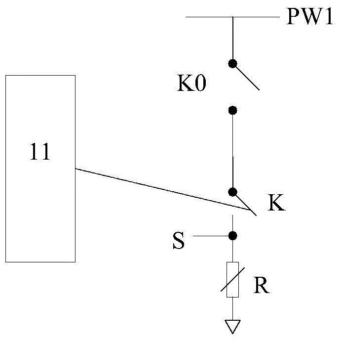
[0039] figure 1 It is a schematic diagram of the switch output channel detection structure provided by Embodiment 1 of the present invention. Such as figure 1 As shown, the switch output channel detection structure provided by the embodiment of the present invention includes:

[0040] Switch output channel 11, output switch K, safety switch K0 and power supply PW1, wherein the power supply PW1 is connected to the output switch K, the safety switch K0 is arranged between the power supply PW1 and the output switch K, and the switch The output terminal of the quantity output channel 11 is connected to the output switch K, so that the driving signal output by the switch quantity output channel 11 controls the turning off and closing of the output switch K. The output switch K outputs to the field load R.

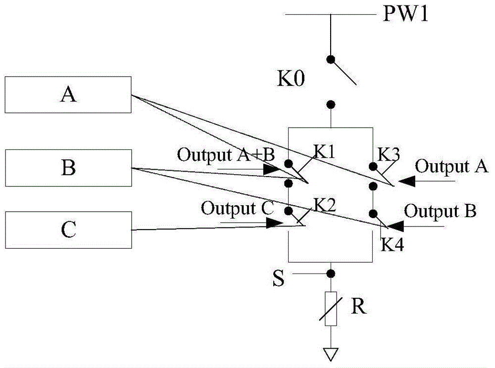
[0041] It should be noted that, in the embodiment of the present invention, the switching value output channel 11 can be a single output channel, and the output switch K cont...

Embodiment 2

[0061] Figure 4 It is a schematic flow chart of the method for detecting the switching output channel provided by the second embodiment of the present invention. Such as Figure 4 shown, which includes the following steps:

[0062] S401. The input terminal of the switching value output channel receives an initial control signal, and converts the initial control signal into a driving signal for controlling the output switch:

[0063] The input end of the switching value output channel receives the initial control signal sent by the microprocessor MCU, and the switching value output channel uses an internal circuit to convert the initial control signal into a driving signal for controlling the output switch.

[0064] S402. Using the drive signal to control the output switch:

[0065] S403. Detect the control result of the output switch:

[0066] As a specific embodiment of the present invention, the control result of detecting the output switch specifically includes: detect...

Embodiment approach

[0081] In addition, in the circuit where the switching value output channel is located, when a slight fault occurs in the switching value output channel, the circuit where the switching value output channel is located can continue to be used. Therefore, in order to improve the availability of the circuit where the switching value output channel is located, the safety switch is disconnected only when the fault of the switching value output channel is determined to be a serious fault. For this reason, the embodiment of the present invention also provides another implementation manner of the detection method of the switching value output channel, the second specific embodiment.

[0082] Embodiment two

[0083] Figure 5 It is a schematic flow chart of the method for detecting the switching output channel provided by the second embodiment of the present invention. Such as Figure 5 As shown, the detection method includes the following steps:


PUM


Abstract

The invention provides a switch signal output channel detection structure and a detection method. The structure comprises a switch signal output channel, an output switch, a safety switch and a power supply, wherein the safety switch is arranged between the power supply and the output switch; and the output end of the switch signal output channel is connected with the output switch. After the fact that fault happens inside or outside the switch signal output channel is detected, the safety switch is controlled to be off, the fault and the switch signal output channel can thus be isolated, the switch signal output channel is thus in a safety state, and the fault processing ability and safety of the overall safety instrument system can be improved.

Description

technical field [0001] The invention relates to the technical field of safety instrument systems, in particular to a detection method and structure of a switching value output channel. Background technique [0002] At present, SIS (Safety Instrumented System) safety instrumented system is widely used in large-scale process control fields such as petroleum and chemical industry, but as a highly reliable safety protection facility, it is also widely used in other industries, including nuclear power, aviation, ships, and high-speed railways and other systems. It is a programmable control system that can respond and protect in time to the possible dangers of petrochemical and other production equipment or the state that will continue to deteriorate if no measures are taken. It can make the production equipment enter a predefined safe shutdown condition ( That is, the output channel is disconnected), so that the risk is reduced to an acceptable minimum level, and the personnel a...

Claims


Application Information

Patent Timeline
Patent Type & Authority Applications(China)
IPC IPC(8): G05B23/02
CPCG05B23/0278
Inventor 董良健张颂姚杰朱杰
Owner ZHEJIANG SUPCON TECH
Why Eureka
Try Eureka