System and method for phase balancing in a power distribution system

a power distribution system and phase balancing technology, applied in the direction of dc network circuit arrangement, dc source parallel operation, ac network load forecast, etc., can solve the problems of high unbalance, voltage imbalance, uneven distribution of single phase load, etc., to minimize the voltage unbalance

Inactive Publication Date: 2015-05-26
GENERAL ELECTRIC CO
View PDF10 Cites 2 Cited by
  • Summary
  • Abstract
  • Description
  • Claims
  • Application Information

AI Technical Summary

Benefits of technology

[0005]In accordance with an embodiment of the present invention, a phase balancing system for a distribution system is provided. The system includes a load forecasting module to determine a load forecast for the distribution system for a period of interest. The system also includes a phase unbalance identification module to determine voltage unbalance on the distribution system for the period of interest and a demand response module to estimate an available demand response on the distribution system for the period of interest. The demand response module is further configured to allocate an optimized demand response from the available demand response to minimize the voltage unbalance on the distribution system for the period of interest.
[0006]In accordance with another embodiment of the present invention, a method for phase balancing in a distribution system is provided. The method includes determining a load forecast for the distribution system for a period of interest and determining a voltage unbalance on the distribution system for the period of interest. The method also includes estimating an available demand response on the distribution system for the period of interest and allocating an optimized demand response from available demand response to minimize the voltage unbalance on the distribution system.
[0007]In accordance with yet another embodiment of the present invention, computer-readable medium comprising computer-readable instructions of a computer program that, when executed by a processor, cause the processor to perform a method for phase balancing in a distribution system is provided. The method includes determining a load forecast for the distribution system for a period of interest and determining a voltage unbalance on the distribution system for the period of interest. The method also includes estimating an available demand response on the distribution system for the period of interest and allocating an optimized demand response from available demand response to minimize the voltage unbalance on the distribution system.

Problems solved by technology

Generally, transmission systems are balanced, but distribution power systems, are highly unbalanced.
Some of the sources of imbalances include asymmetrical winding impedances of distribution transformers and asymmetrical line impedances.
The main source of voltage imbalance at distribution points is the uneven distribution of single phase loads.
Another source of imbalance is a fault or other interruption (e.g. for maintenance) along a single phase line.
Further, the energy consumption by these loads changes continuously, making the balancing process challenging.
Effects of phase imbalances include increased line losses and heating, equipment overloading, and decreased system stability.
Unbalanced phase currents create neutral current flows (if neutral path exists) leading to additional losses (neutral line losses) on the system.
Unbalanced voltages are an issue for three phase loads like induction motors or power-electronic converters, as the negative and zero sequence currents create additional losses.
Unbalanced currents also lead to torque pulsations, increased vibrations and mechanical stresses, increased losses, and motor overheating and thus degrades the performance and shortens the life of the induction motors.
In power electronic converters, the effects of unbalanced voltages include increased input current distortion, generation of twice the fundamental frequency voltage ripple in the DC link and an increased reactive power.
There is currently a very limited ability to alleviate phase imbalances on distribution systems.
However, the switching is performed in a discrete manner and it cannot dynamically balance the system load.
These are costly solutions, however, since they require additional capital investments to add equipment to the system.
Further, they are not dynamic and may also inject harmonics into the system.

Method used


Image

  • System and method for phase balancing in a power distribution system
  • System and method for phase balancing in a power distribution system
  • System and method for phase balancing in a power distribution system

Examples


Embodiment Construction

[0014]When introducing elements of various embodiments of the present invention, the articles “a,”“an,”“the,” and “said” are intended to mean that there are one or more of the elements. The terms “comprising,”“including,” and “having” are intended to be inclusive and mean that there may be additional elements other than the listed elements.

[0015]As used herein, the term “module” refers to software, hardware, or firmware, or any combination of these, or any system, process, or functionality that performs or facilitates the processes described herein.

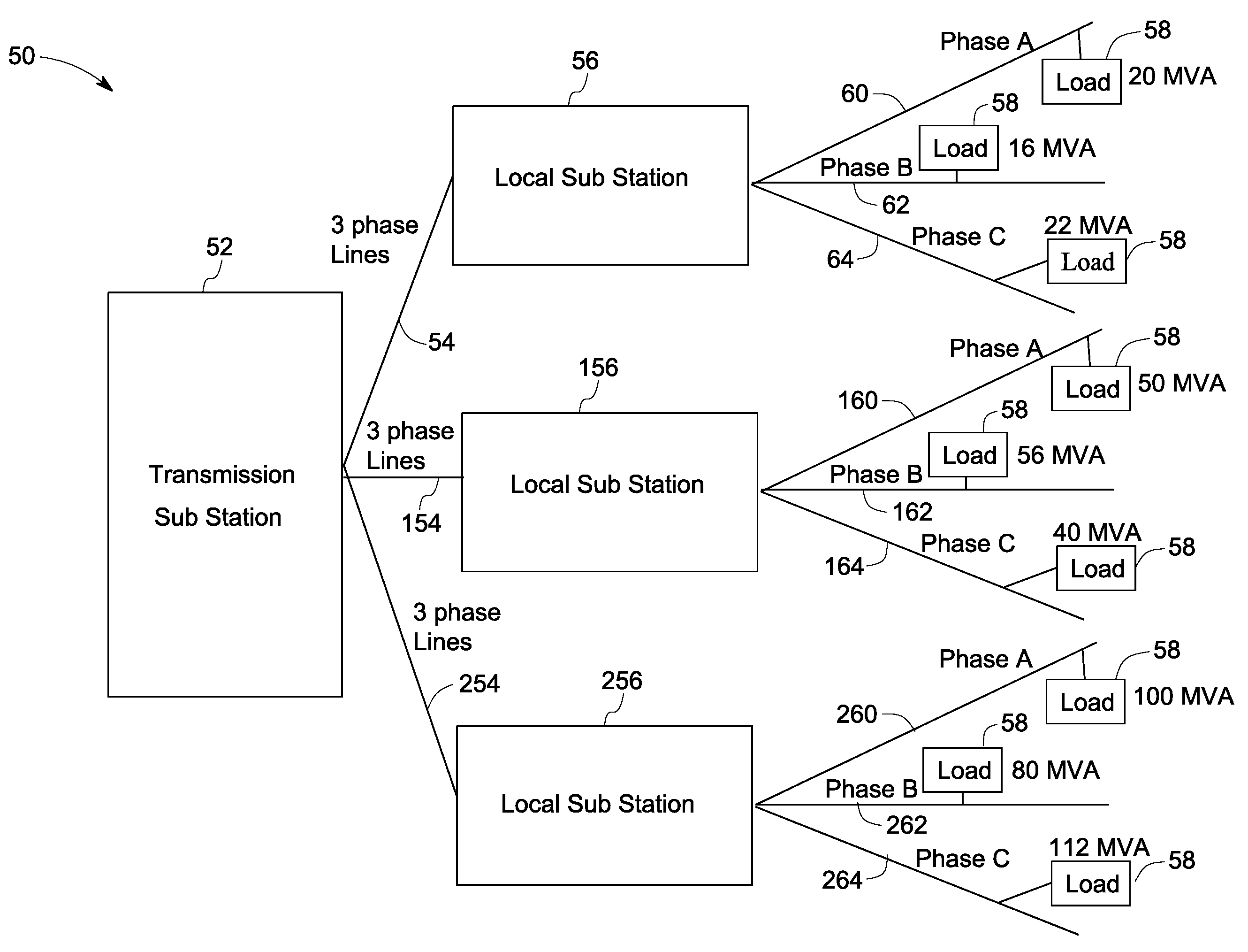
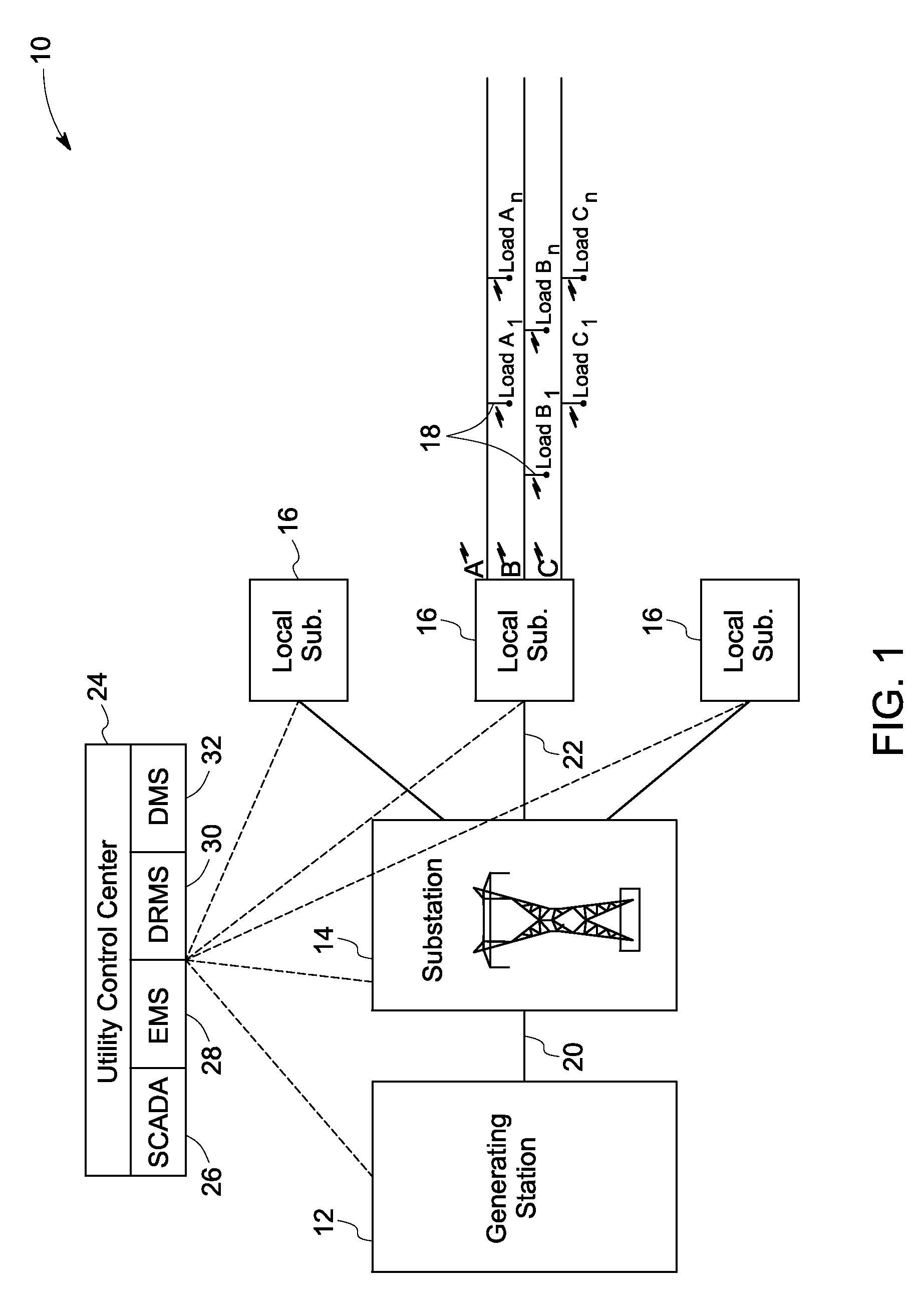
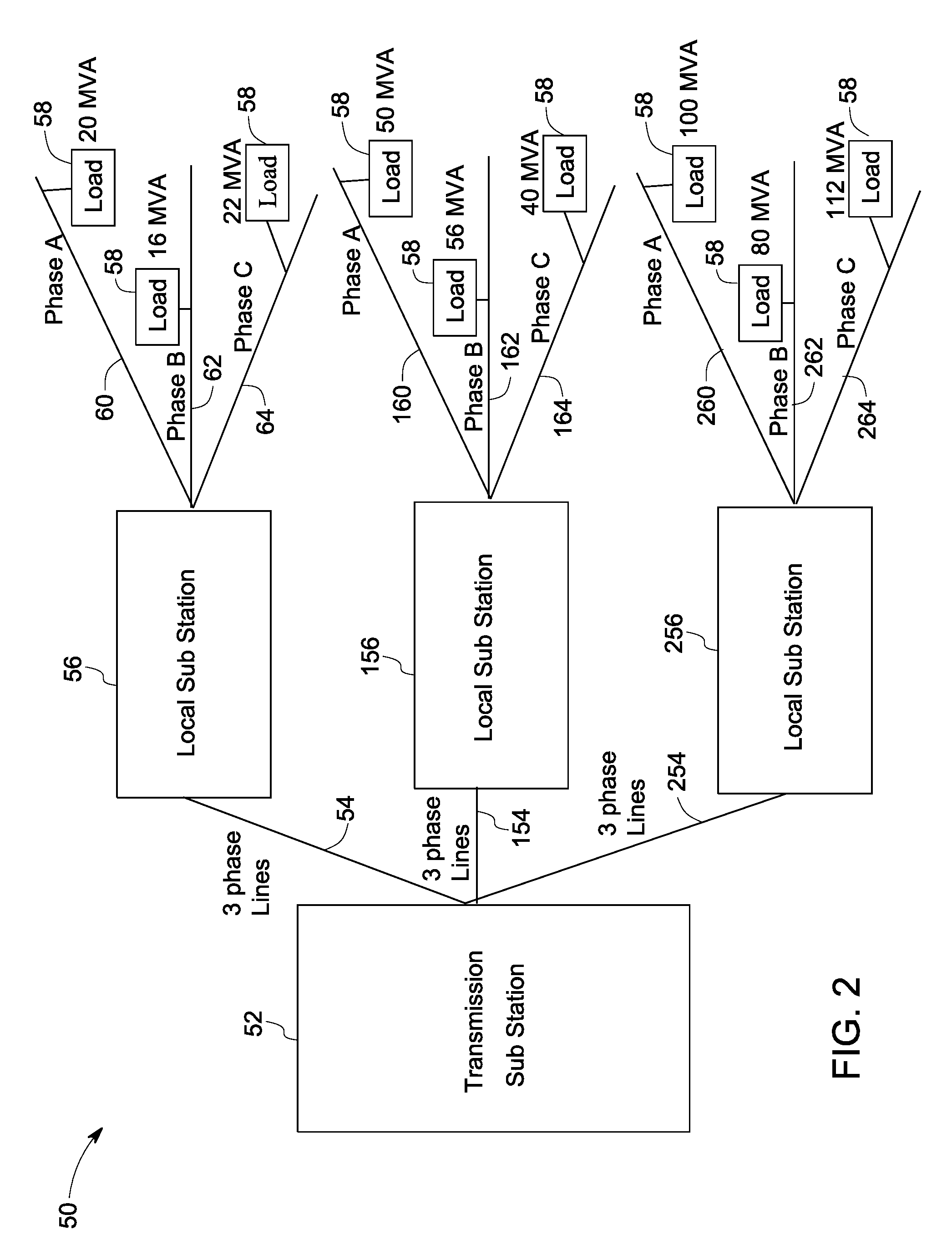
[0016]FIG. 1 illustrates a single line diagram of an overall electric system 10 from generation to utilization. The electric system 10 includes a generating station 12, a transmission substation 14, local substations or distribution substations 16 and loads 18. Generating station 12 may be a hydropower generating station, a thermal power generating station, a wind power generating station or a solar power generating station, for example. ...


PUM


Abstract

A phase balancing system includes a load forecasting module, a phase unbalance identification module and a demand response module. The load forecasting module determines a load forecast for the distribution system for the period of interest and the phase unbalance identification module determines voltage unbalance on the distribution system for the period of interest. The demand response module estimates an available demand response on the distribution system for the period of interest and allocates an optimized demand response from the available demand response to minimize the voltage unbalance on the distribution system for the period of interest.

Description

BACKGROUND[0001]In a balanced three-phase power system, the individual phase quantities (voltages / currents) are equal in magnitude and are displaced with respect to each other by 120°. Generally, transmission systems are balanced, but distribution power systems, are highly unbalanced. Some of the sources of imbalances include asymmetrical winding impedances of distribution transformers and asymmetrical line impedances. The main source of voltage imbalance at distribution points is the uneven distribution of single phase loads. Another source of imbalance is a fault or other interruption (e.g. for maintenance) along a single phase line. This would create a need for short term balancing until the affected line can be brought back into service. Further, the energy consumption by these loads changes continuously, making the balancing process challenging.[0002]Effects of phase imbalances include increased line losses and heating, equipment overloading, and decreased system stability. Unb...

Claims


Application Information

Patent Timeline
Patent Type & Authority Patents(United States)
IPC IPC(8): H02J3/26H02J1/10H02J3/00
CPCH02J3/26Y02E40/50H02J3/003Y04S10/50
Inventor BLACK, JASON WAYNETINNIUM, KANNAN NATARAJANLARSON, RONALD RAYWANG, XIAOFENGJOHAL, HARJEET
Owner GENERAL ELECTRIC CO
Why Eureka
Try Eureka