Power management device of a touchable control system

a power management device and touchable control technology, applied in the direction of electric variable regulation, process and machine control, instruments, etc., can solve the problems of slowness or delay of users with the conventional touchable control system, and achieve the effect of significantly reducing the response time of restoring the sleep mode to the operating mod

Active Publication Date: 2015-05-26
EGALAX EMPIA TECH INC
View PDF6 Cites 0 Cited by
  • Summary
  • Abstract
  • Description
  • Claims
  • Application Information

AI Technical Summary

Benefits of technology

[0009]In view of the foregoing, an embodiment of the present invention provides a power management device of a touchable control system for providing a rapid response to the sleep mode of the touchable control system. Applying the power management device of a touchable control system of the present invention to a mobile phone, a computer or an electronic system having a touchable screen can make the electronic system rapidly restore the sleep mode to the operating mode. That is, the response time of restoring the sleep mode to the operating mode can significantly decrease such that the users can use the electronic system more conveniently and rapidly.

Problems solved by technology

However, the output current IO do not fully flow to the external capacitor Cext but the loading circuit consumes a part of the output current Io, wherein the consuming output current IO is the loading current ILoad.
Although the charge time may be only few microseconds, which still make the users feel slow or delay with the conventional touchable control system.

Method used


Image

  • Power management device of a touchable control system
  • Power management device of a touchable control system
  • Power management device of a touchable control system

Examples


Embodiment Construction

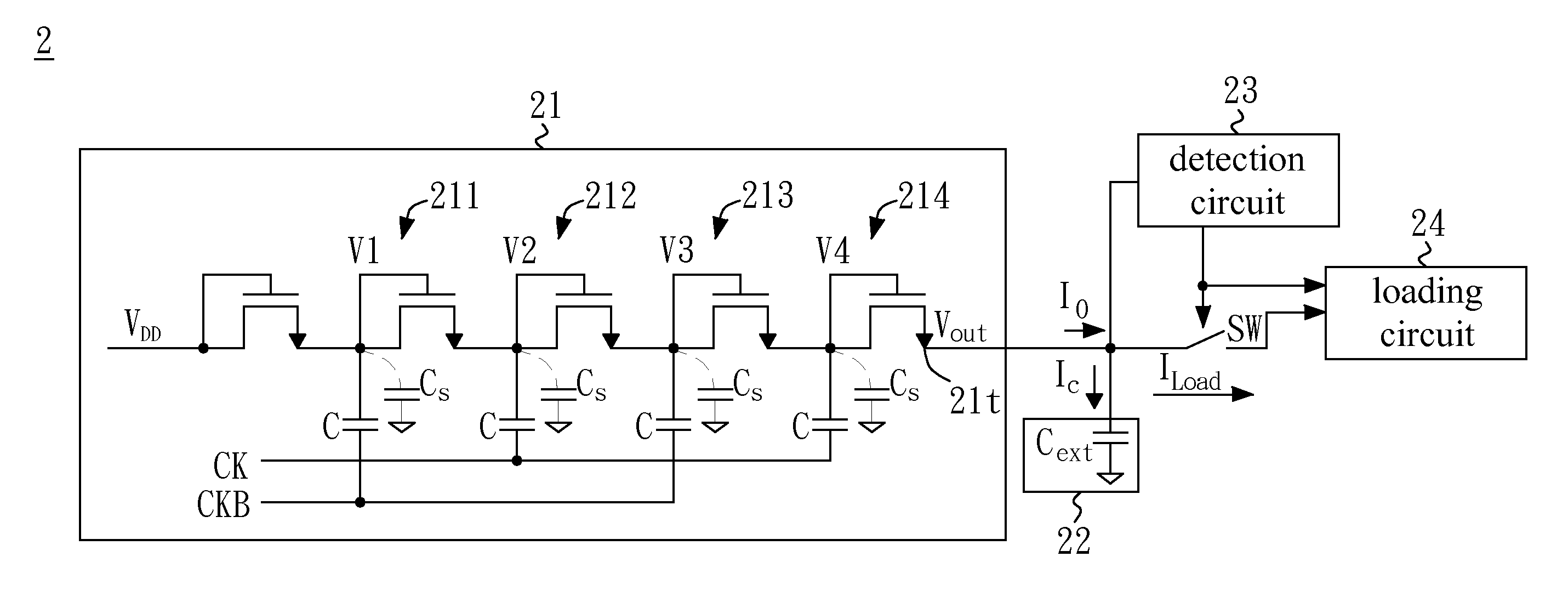
[0017]FIG. 2A shows the schematic circuit of the power management device of the touchable control system of the present invention. The power management device includes a boost circuit 21, a storage circuit 22, a detection circuit 23 and a loading circuit 24. The boost circuit 21 has an output terminal 21t and generates an output voltage Vout and an output current Io. The storage circuit 22 electrically connects to the output terminal 21t of the boost circuit 21 and stores the output voltage Vout. The detection circuit 23 electrically connects to the storage circuit 22 so as to detect the output voltage Vout. The loading circuit 24 electrically connects or disconnects to the output terminal 21t of the boost circuit 21 according to a predetermined value of the output voltage Vout.

[0018]In an embodiment, the boost circuit 21 may be implemented to provide the output voltage Vout by a variety of voltage converting circuits such as a voltage regulator or a charge pump. The charge pump com...


PUM


Abstract

A power management device of a touchable control system includes a boost circuit, a storage circuit, a detection circuit and a loading circuit. The boost circuit has an output terminal and generates an output voltage. The storage circuit electrically connects to the output terminal of the boost circuit and stores the output voltage. The detection circuit electrically connects to the storage circuit so as to detect the output voltage. The loading circuit electrically connects or disconnects to the output terminal of the boost circuit according to a predetermined value of the output voltage.

Description

BACKGROUND OF THE INVENTION[0001]1. Field of the Invention[0002]The present invention generally relates to a touchable control system, and more particularly to a power management device of a touchable control system for rapidly replying to a sleep mode.[0003]2. Description of Related Art[0004]A touch panel may be combined with a display screen to result in a touch screen. Touch screens have been widely used as input interfaces for electronic devices for detecting touch inputs within a display area. If no touch inputs input to the touch screen, users usually close the power supplied to the touch screen to enable the sleep mode for avoiding the unnecessary power consumption.[0005]FIG. 1A shows a schematic circuit of a power management device 1 of a conventional touchable control system. As mentioned above, if the power of the touch screen is closed to enable the sleep mode, there are neither input signals of VDD and CK / CKB, nor output voltage Vout and the loading circuit is disabled, ...

Claims


Application Information

Patent Timeline
Patent Type & Authority Patents(United States)
IPC IPC(8): H02M3/18H02M7/00G05F1/10G05F3/02H02M3/07
CPCH02M3/07H02M3/073
Inventor LIN, PO-CHUAN
Owner EGALAX EMPIA TECH INC
Why Eureka
Try Eureka