Infrared security sensor

a technology of infrared security and sensor device, which is applied in the direction of optical detection, optical radiation measurement, instruments, etc., can solve the problem of difficult adjustment of optical axis, and achieve the effect of facilitating the optical axis easily and smoothly

Active Publication Date: 2015-06-02
OPTEX CO LTD
View PDF7 Cites 0 Cited by
  • Summary
  • Abstract
  • Description
  • Claims
  • Application Information

AI Technical Summary

Benefits of technology

[0010]In view of the foregoing, the present invention has been devised to eliminate the problems and inconveniences in the prior art security devices discussed above and is intended to provide an infrared security sensor device capable of facilitating the optical axis easily and smoothly when the light receiving sensitivity is to be controlled by means of a light projecting power control.
[0012]According to the present invention, since when the detection signal level (light receiving sensitivity) is adjusted by means of the light projecting power control, the manual adjustment of the light projecting power can be selected in the plurality of the steps at the time of the optical axis adjustment, a change occurring in the level display for each of the selected steps can be clearly confirmed and there is no possibility that the level display considerably changes without knowing the steps such as observed in the conventional art, and, therefore, the attendant worker is prevented from being unnecessarily annoyed or confused. Accordingly, when the light receiving sensitivity is to be adjusted by means of the light projecting power, the optical axis adjustment can be easily and smoothly accomplished.
[0013]In a preferred embodiment of the present invention, the light projector and the light receiver may have respective removable coverings; in which case the light projecting power control unit includes a covering transmittance adjusting sector for automatically adjusting the light projecting power in dependence on the amount of the light transmittance reduced by the covering, in addition to the manual adjustment or the automatic adjustment of the light projecting power during the optical axis adjustment, under a condition in which the coverings of the light projector and the light receiver are removed, when the coverings are mounted on the light projector and the light receiver subsequent to termination of the optical axis. Accordingly, the reduction of the light projecting power caused by the mounting of the covering can be automatically compensated for.

Problems solved by technology

For this reason, when the light projecting power is automatically varied in the plurality of steps during the optical axis adjustment, a plurality of level displays in the display unit considerably move up and down automatically according to the steps thereof and, therefore, because of a large change in level displays under a condition in which no specific step is not clear, the attendant worker will be unnecessarily annoyed and, thus, it will often occur that the optical adjustment is difficult to achieve.

Method used


Image

  • Infrared security sensor
  • Infrared security sensor
  • Infrared security sensor

Examples


Embodiment Construction

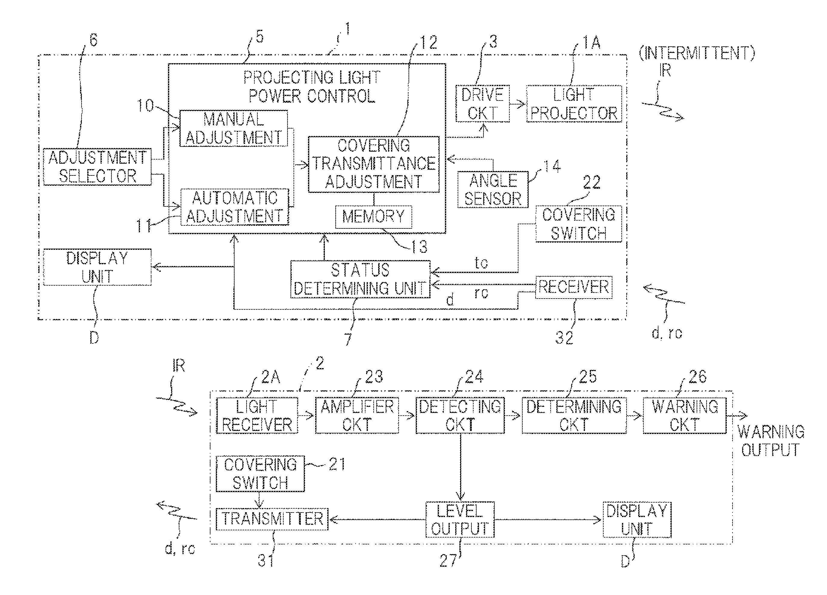
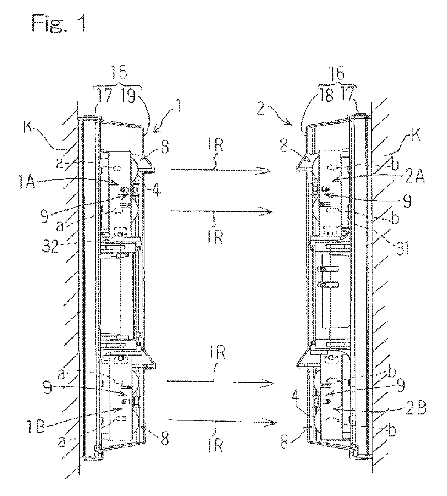
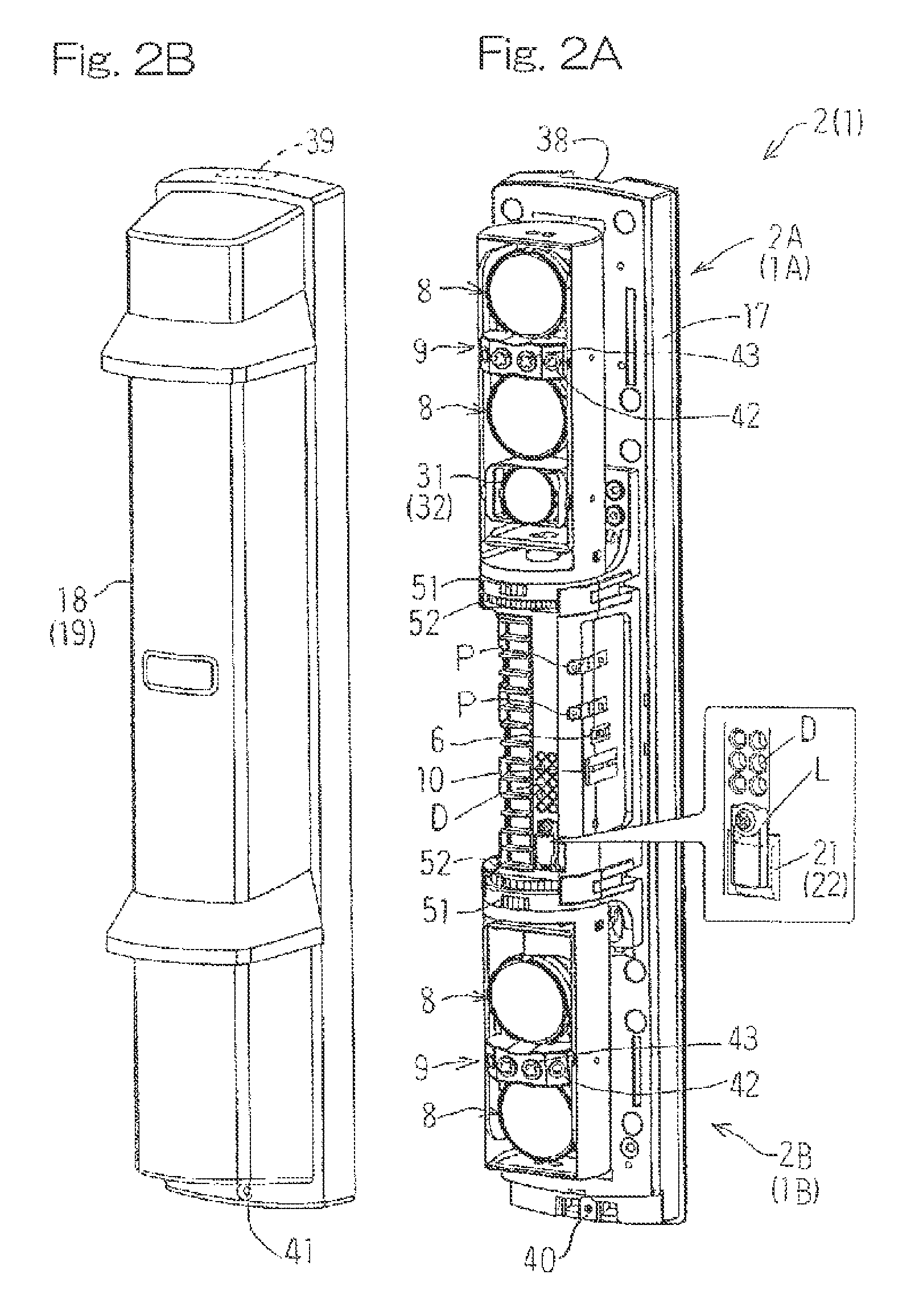
[0020]Hereinafter, a preferred embodiment of the present invention will be described in detail with reference to the accompanying drawings. In particular, FIG. 1 illustrates a schematic side view of an infrared security sensor device designed in accordance with the preferred embodiment of the present invention; FIG. 2A illustrates, in a perspective representation, a light projecting unit (a light receiving unit) of the infrared security sensor device with a covering removed; and FIG. 2B illustrates the covering of the light projecting unit. As shown in FIG. 1, the infrared security sensor device includes a light projecting unit 1 and a light receiving unit 2. The light projecting unit 1 in turn includes first and second light projectors 1A and 1B positioned one above the other and each made up of first and second light projecting elements a and a such as, for example, infrared light emitting diodes, whereas the light receiving unit 2 in turn includes first and second light receivers...


PUM


Abstract

An infrared security sensor device includes a light projector 1A, 1B having a projecting light power control unit 5 for controlling the light receiving sensitivity of a light receiver 2A, 2B by switching a light projecting power thereof to one of a plurality of steps in dependence on the level of a detection signal and a status determining unit 7 for determining an optical axis adjusting time and an alert time. The light projector 1A, 1B is further provided with an adjustment selecting sector 6 capable of selecting one of the manual and automatic adjusting sectors 10 and 11 such that during the optical axis adjustment the light projecting power can be manually adjusted by the manual adjusting sector 10.

Description

CROSS REFERENCE TO THE RELATED APPLICATION[0001]This application is based on and claims Convention priority to Japanese patent application No. 2012-017662, filed on Jan. 31, 2012, the entire disclosure of which is herein incorporated by reference as a part of this application.BACKGROUND OF THE INVENTION[0002]1. Field of the Invention[0003]The present invention relates to an infrared security sensor device of a kind equipped with a light projecting unit for projecting an infrared beam for object detection purpose, a light receiving unit for receiving the projected infrared beam and then outputting a detection signal, and an optical alignment unit for adjusting an optical axis between the light projecting unit and the light receiving unit.[0004]2. Description of the Prior Art[0005]The infrared security sensor device of an active type generally includes a light projecting unit having a light projecting element, a light receiving unit having a light receiving element and a sighting devi...

Claims


Application Information

Patent Timeline
Patent Type & Authority Patents(United States)
IPC IPC(8): G01V8/12
CPCG01V8/12
Inventor MAKINO, HIROSHIHAYASHIDE, KOJI
Owner OPTEX CO LTD
Why Eureka
Try Eureka