Riding walkers having pedal drive assemblies

a technology of pedal drive and walking walkers, which is applied in the direction of wheelchair/patient conveyance, transportation and packaging, cycles, etc., can solve the problems of heavy and expensive electric wheelchairs, tiring operation for those with limited strength, etc., and achieves the effects of convenient portability, low cost and light weigh

Inactive Publication Date: 2015-06-09
WHITENER PHILIP C
View PDF6 Cites 3 Cited by
  • Summary
  • Abstract
  • Description
  • Claims
  • Application Information

AI Technical Summary

Benefits of technology

[0003]Systems and methods for riding walkers having a pedal drive assembly are disclosed. Embodiments of systems and methods in accordance with the teachings of the present disclosure may advantageously enable a user to enjoy the usual and customary benefits of conventional wheel chair apparatus and walker apparatus, but also provide additional capability with respect to speed and mobility, and to exercise their legs using the pedal drive assembly whenever they so desire. Embodiments in accordance with the present disclosure may also meet the need for a low cost, light weight, easily portable device that transports an occupant at reasonable speed using minimal energy.
[0004]In at least some embodiments, using riding walker assemblies in accordance with the present disclosure, a user may exercise their legs while in a seated position, and may travel along a desired travel path while in a seated position without the need for exerting their upper body. Providing the capability to pedal in accordance with the present disclosure may have considerable therapeutic and physiological advantages over conventional assemblies which require a user to walk upright to exercise their legs. Similarly, providing a capability to travel while in a seated position using the pedal drive assembly may provide considerable advantages to those users who have healthy legs and who may not have healthy arms or upper body as required by conventional wheel chair apparatus.

Problems solved by technology

Although the wheeled walker greatly improves mobility for short distances, the operation is tiring for those with limited strength.
At present heavy and expensive electric wheelchairs are prescribed for such cases.

Method used


Image

  • Riding walkers having pedal drive assemblies
  • Riding walkers having pedal drive assemblies
  • Riding walkers having pedal drive assemblies

Examples


Embodiment Construction

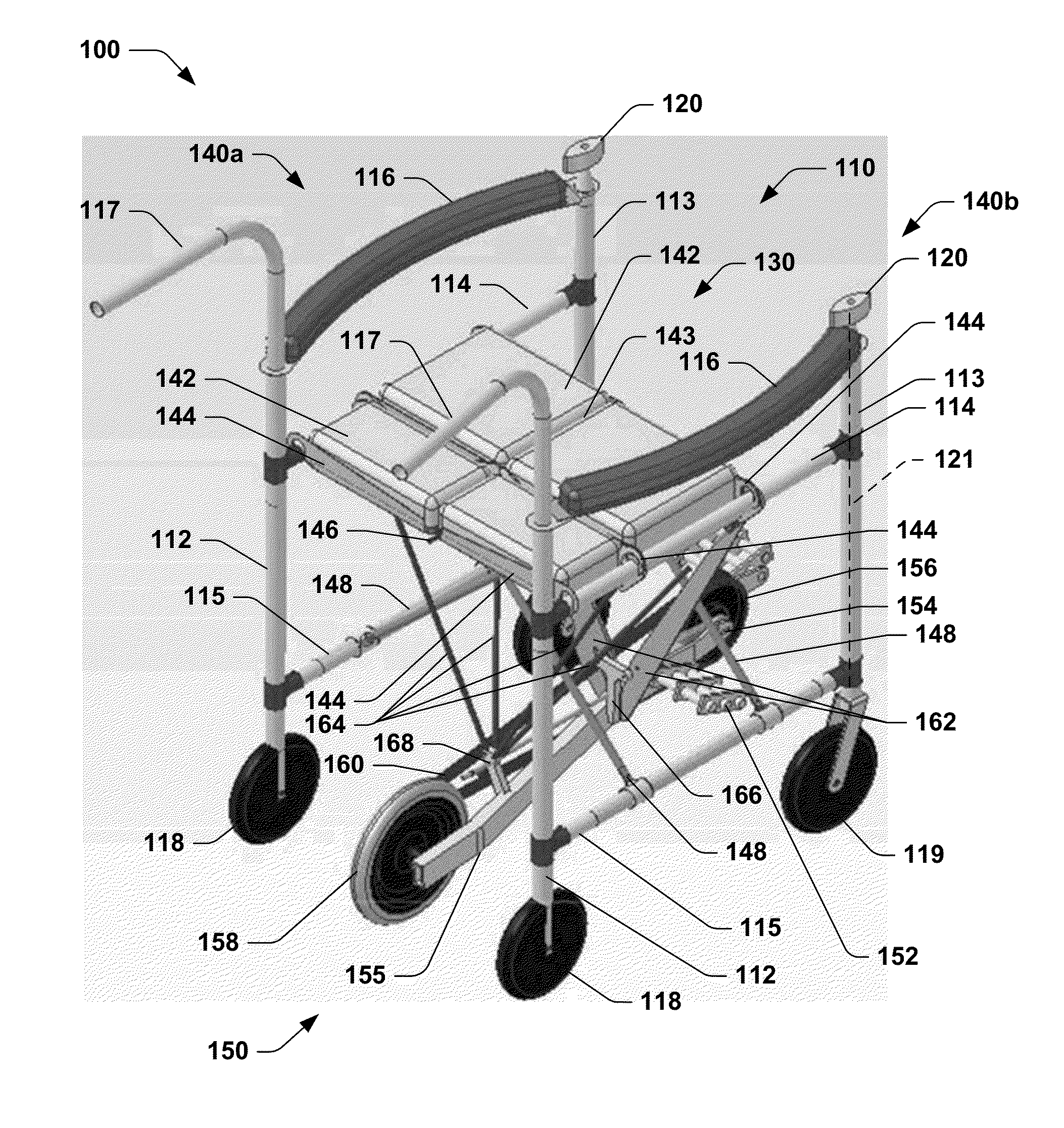
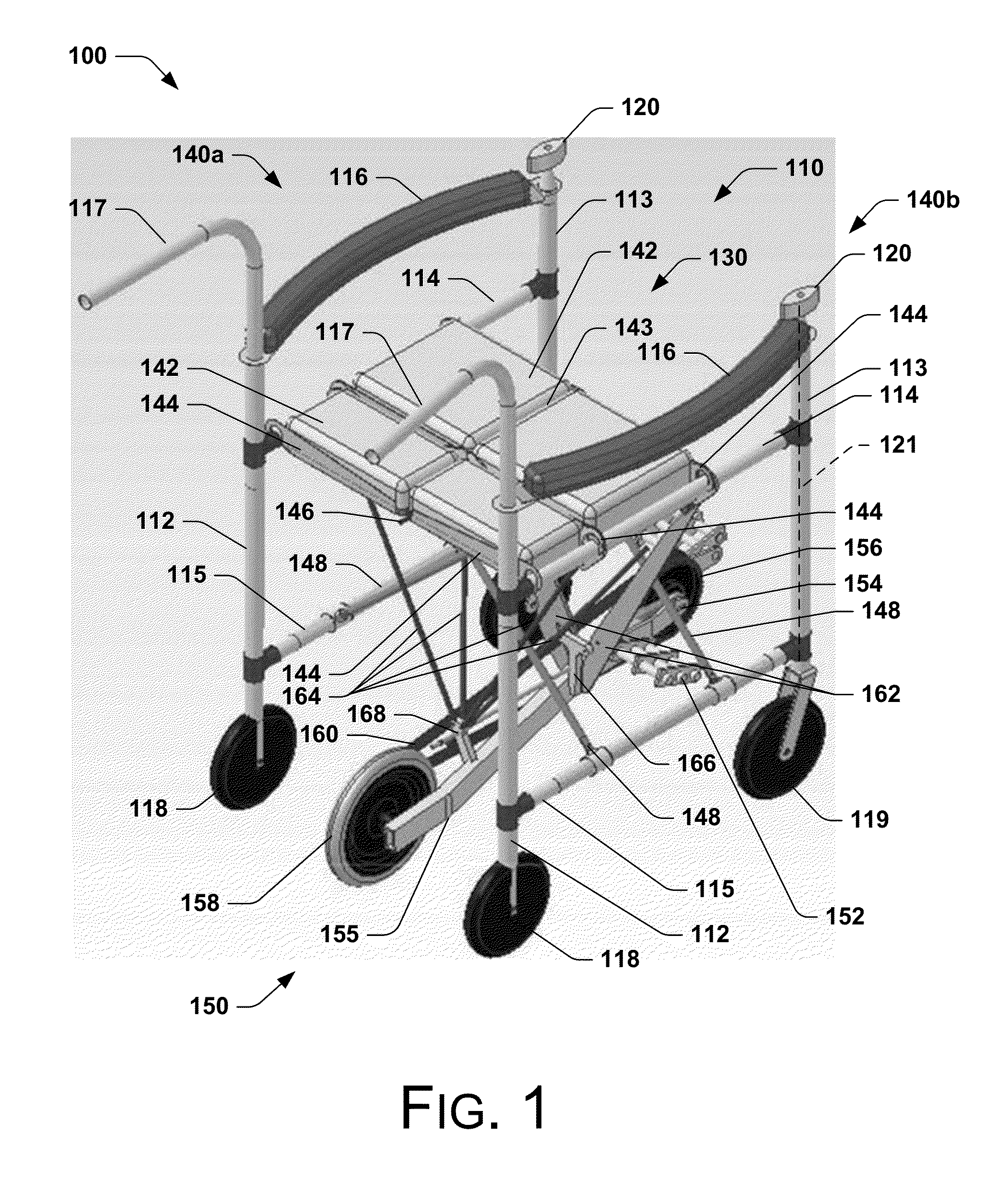
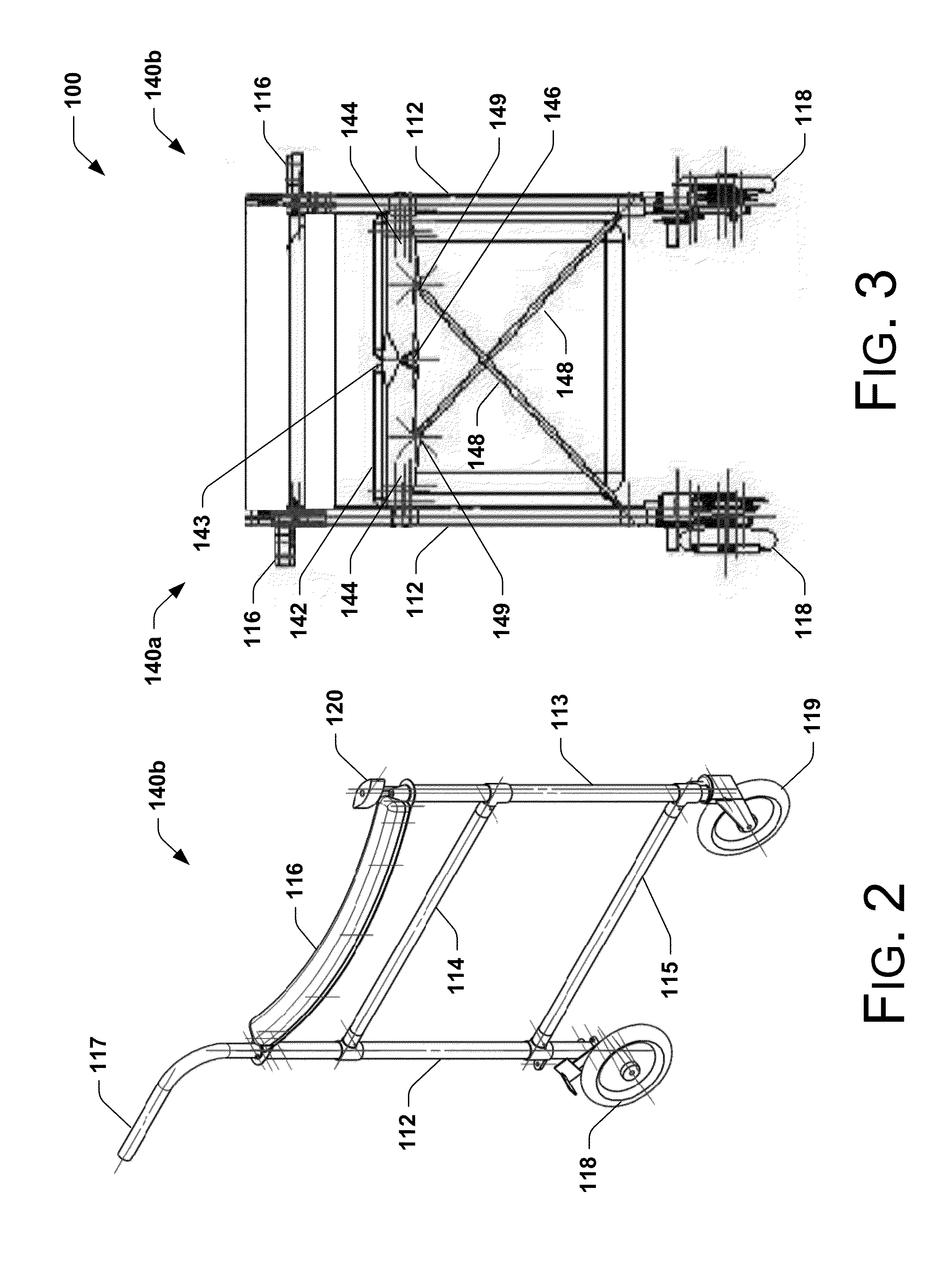
[0030]The present disclosure is directed to systems and methods for riding walker assemblies having a drive assembly. Many details of specific embodiments in accordance with the present disclosure are set forth in the following description and in FIGS. 1-22 to provide a thorough understanding of such embodiments. One skilled in the art, however, will understand that the present invention may have additional embodiments, and that alternate embodiments of the invention may be practiced without one or more of the details described in the following description.

[0031]FIG. 1 is an isometric view of an embodiment of a riding walker assembly 100 in accordance with the teachings of the present disclosure. In this embodiment, the riding walker assembly 100 includes a frame assembly 110 having a seat assembly 130, and a pedal drive assembly 150 that enables a user (not shown) to propel the riding walker assembly 100 using their legs while seated on the seat 130.

[0032]More specifically, in the ...


PUM


Abstract

In at least some embodiments, a riding walker assembly includes a support assembly and a drive assembly. The support assembly may include a frame work supporting a seat assembly, and a plurality of wheels operatively coupled to the frame work and configured to rollably engage a floor surface. The drive assembly may include a drive wheel configured to engage the floor surface, and a pedal assembly operatively coupled to the drive wheel such that rotation of the pedal assembly rotates the drive wheel. The riding walker assembly may further include a coupling assembly operatively coupling the drive assembly to the support assembly, the coupling assembly being configured to selectively engage and disengage the drive wheel from the floor surface.

Description

FIELD OF THE INVENTION[0001]The present disclosure is directed to walker apparatus and methods, and more specifically, to riding walkers having a pedal drive assembly.BACKGROUND OF THE INVENTION[0002]Walkers and wheelchairs are popular devices for assisting people with mobility. Conventional walkers typically provide a stable base which provides support when the person is taking steps, and then is lifted and moved to a new location, enabling the person takes additional steps. Such walkers have evolved to a 4 wheel configuration that includes a seat permitting a person to rest or to be pushed by an attendant. Although the wheeled walker greatly improves mobility for short distances, the operation is tiring for those with limited strength. At present heavy and expensive electric wheelchairs are prescribed for such cases. Alternately, wheelchairs typically allow a person to move without exerting their legs by means of an attendant or by drive wheels that are driven using the person's a...

Claims


Application Information

Patent Timeline
Patent Type & Authority Patents(United States)
IPC IPC(8): B62M9/00B62M1/36
CPCB62M1/36B62K3/002A61G5/026A61H3/04A61H2003/043A61H2003/046A61H2201/0161A61H2201/1261A61H2201/1633A61G5/0825A61G5/0891A61G5/1051A61G5/125
Inventor WHITENER, PHILIP C.
Owner WHITENER PHILIP C
Why Eureka
Try Eureka