Developing apparatus

a technology of developing apparatus and a development platform, which is applied in the direction of electrographic process apparatus, instruments, optics, etc., can solve the problems of reducing the performance of the developer in terms of the conveyance of the developer, the scattering of toner, and the scratching of the fixed toner imag

Active Publication Date: 2015-06-09
CANON KK
View PDF23 Cites 2 Cited by
  • Summary
  • Abstract
  • Description
  • Claims
  • Application Information

AI Technical Summary

Benefits of technology

[0006]Thus, the primary object of the present invention is to provide a developing apparatus (device) which can output images which suffer significantly less from the nonuniformity in density attributable to groove pitch, compared to any conventional developing device, while being able to prevent foreign substances from becoming stuck between its regulating blade and development sleeve.

Problems solved by technology

However, as a development sleeve increases in the length of usage, its peripheral surface is worn, and therefore, reduces in its performance in terms of developer conveyance.
However, increasing a development sleeve in peripheral velocity as disclosed in Patent Document 1 is problematic in that it is likely to cause toner to be scattered, and / or a fixed toner image to be scratched by magnetic brush.
Therefore, it is likely to cause a developing device to output images of low quality.
Thus, it is likely for foreign substance in developer to be stuck between the regulation blade and sleeve.

Method used


Image

  • Developing apparatus
  • Developing apparatus
  • Developing apparatus

Examples


embodiment 1

Image Forming Apparatus

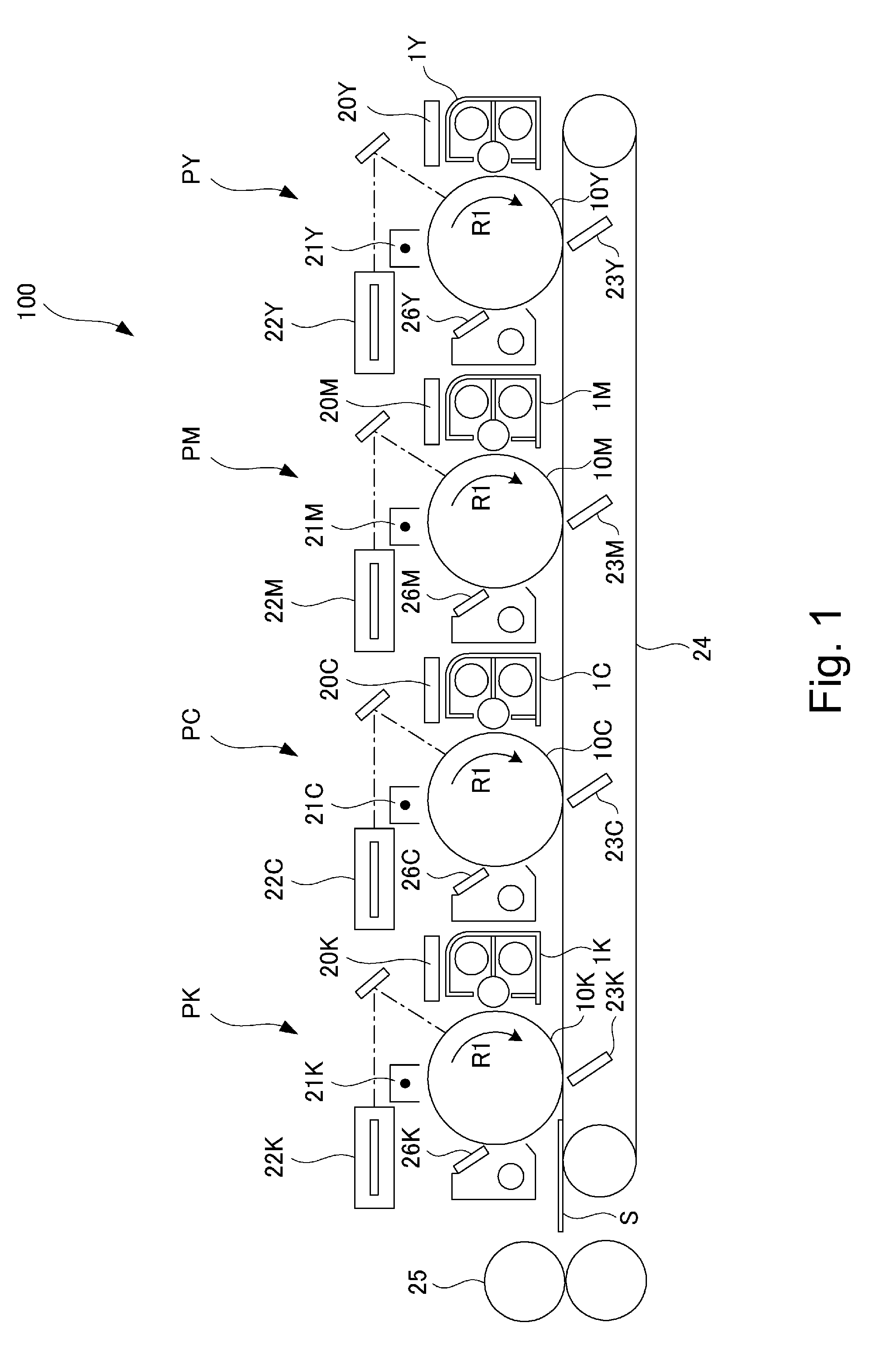
[0018]FIG. 1 is a schematic sectional view of the image forming apparatus in the first embodiment of the present invention. It shows the general structure of the apparatus.

[0019]Referring to FIG. 1, the image forming apparatus 100 is a full-color printer of the so-called tandem type, and also, of the recording medium conveyance belt type. That is, it has a recording medium conveyance belt 24, and yellow (Y), magenta (M), cyan (C) and black (K) image forming stations PY, PM, PC and PK, which correspond in color to the images they form, one for one, and which are aligned in tandem along the recording medium conveyance belt 24.

[0020]To the recording medium conveyance belt 24, sheets S of recording medium are sequentially conveyed from an unshown recording medium cassette with such a timing that the arrival of each sheet S at the image forming station P coincides with the arrival of a toner image on the photosensitive drum 10Y at the image forming station P. In th...

embodiment 2

[0069]Next, referring to FIG. 6, the output of the electric power source 11 of the developing device 1 in the second embodiment of the present invention is described. FIG. 6 is a drawing of the waveform of the development bias outputted by the electric power source 11 of the developing device 1 in the second embodiment. The image forming apparatus 100 and developing device 1 in this embodiment are the same in structure and operation as those in the first embodiment. Therefore, their structural components which are similar to the counterparts in the first embodiment are given the same referential codes as those given to the counterpart, and are not described here, except for their characteristic features.

[0070]In the first embodiment, a SBP was used as the waveform for the development bias. It was varied in the number of blank portions to find out the relationship between the change in the number of blanks and the changes in the severity of the nonuniformity in density, which are att...

embodiment 3

[0082]Next, referring to FIG. 7, the output of the electric power source 11 of the developing device 1 in the third embodiment of the present invention is described. FIG. 7 is a drawing which shows the waveform of the development bias which the electric power source of the developing device 1 in this embodiment outputs. The image forming apparatus 100 and developing device 1 in this embodiment are similar in basic structure and operation, to the image forming apparatuses 100 and developing devices 1 in the first and second embodiments. Therefore, their components which are the same or similar in function, as or to, the counterparts in the first and second embodiments, are given the same referential codes as those given to the counterparts, and are not described here, except for their characteristic features in this embodiment.

[0083]In the second embodiment, the development bias was structured to satisfy the condition ((development time t2


PUM


Abstract

A developing apparatus includes a developer carrying sleeve for carrying a developer to a position opposing an image bearing drum. The sleeve is provided with a plurality of groove portions extending in an axial direction of the sleeve, and a developing bias voltage applying device for applying a developing bias voltage to the sleeve. The bias voltage applying device is capable of outputting, as the bias voltage, a voltage of a waveform having a cyclic period including an AC bias portion having an AC component and a DC component superimposed thereto, and a blank portion following the AC bias portion and consisting of a DC component. A width L (m) of the groove, a peripheral speed Vs (m / s) of the sleeve, and a duration t1 (s) of the blank portion in one cyclic period of the bias voltage satisfy L / Vs<t1.

Description

FIELD OF THE INVENTION AND RELATED ART[0001]The present invention relates to a developing apparatus which is mounted in an image forming apparatus to give developer to an electrostatic latent image formed on an image bearing member of the image forming apparatus, in order to develop the electrostatic latent image into a visible image.[0002]In the field of an image forming apparatus, it has been a common practice to blast the peripheral surface of a development sleeve to roughen the peripheral surface of the development sleeve, in order to enable the development sleeve to satisfactorily bear and carry developer. However, as a development sleeve increases in the length of usage, its peripheral surface is worn, and therefore, reduces in its performance in terms of developer conveyance. In recent years, therefore, there have been proposed various technologies for providing a development sleeve which is relative low in cost, and yet, highly durable and satisfactory in performance in term...

Claims


Application Information

Patent Timeline
Patent Type & Authority Patents(United States)
IPC IPC(8): G03G15/09G03G15/06
CPCG03G15/065
Inventor FURUKAWA, MITSUHIROSAKAMAKI, TOMOYUKI
Owner CANON KK
Why Eureka
Try Eureka