Developing device

a technology of developing device and developer, which is applied in the direction of electrographic process apparatus, instruments, optics, etc., can solve the problems of insufficient development device, difficult to ensure density uniformity of developer, and inferior to ensure the uniformity of image density in a copy page with solid black, so as to achieve the effect of free from density non-uniformity

Active Publication Date: 2013-02-05
KONICA MINOLTA BUSINESS TECH INC
View PDF3 Cites 2 Cited by
  • Summary
  • Abstract
  • Description
  • Claims
  • Application Information

AI Technical Summary

Benefits of technology

[0023]According to the present invention, an excessive developer in a developer standby space is discharged and then the amount of the developer accommodated in the developer standby space is appropriately maintained, whereby no excessive stress is applied to the developer, resulting in the output of a stable image free from density non-uniformity.

Problems solved by technology

However, this developing device is inadequate in terms of uniform stirring of a developer, producing then such a disadvantage that it is inferior to ensure uniformity of image density in a copy page with solid black.
Namely, only when there is simply employed such a constitution in which one stirring and conveying screw feeds a developer to a developing roller and also collects the used developer and a plurality of stirring and conveying screws convey the developer in the axial direction each reversely, it is difficult to ensure density uniformity of the developer.
When the mobility of the developer is degraded, the problem of occurrence of density non-uniformity corresponding to a screw pitch is produced in some cases.
Thereby, produced is such a problem that some additives coated on the external side of the toner particles penetrate into the interior of the toner via friction with a carrier, resulting in a decrease in developer mobility.
Further, when the gap is excessively widened, the amount falling down is increased and the amount remaining in the developer standby space 50A is decreased, whereby the amount of the developer feedable to the developing roller 41 is decreased, resulting in the problem that developer feeding to the developing roller 41 becomes unstable.
When such an excessive stress is applied to the developer, the mobility of the toner is degraded due to burying of additives, and the charging performance of the carrier is deteriorated due to abrasion of the coated layer on the surface thereof, resulting in such a problem that image density non-uniformity tends to occur and then image quality is degraded.
Further, due to an increase in the friction force between the toner and the carrier in the developing device, the temperature therein is increased, resulting in such a problem that the toner is easily softened.
When the toner is softened, additives coated on the toner tend to penetrate into the interior of the toner, whereby there are produced such problems that adhesion force to the carrier is further increased and the softened toner is liable to adhere to various portions of the image forming apparatus.

Method used


Image

  • Developing device
  • Developing device
  • Developing device

Examples


example 1

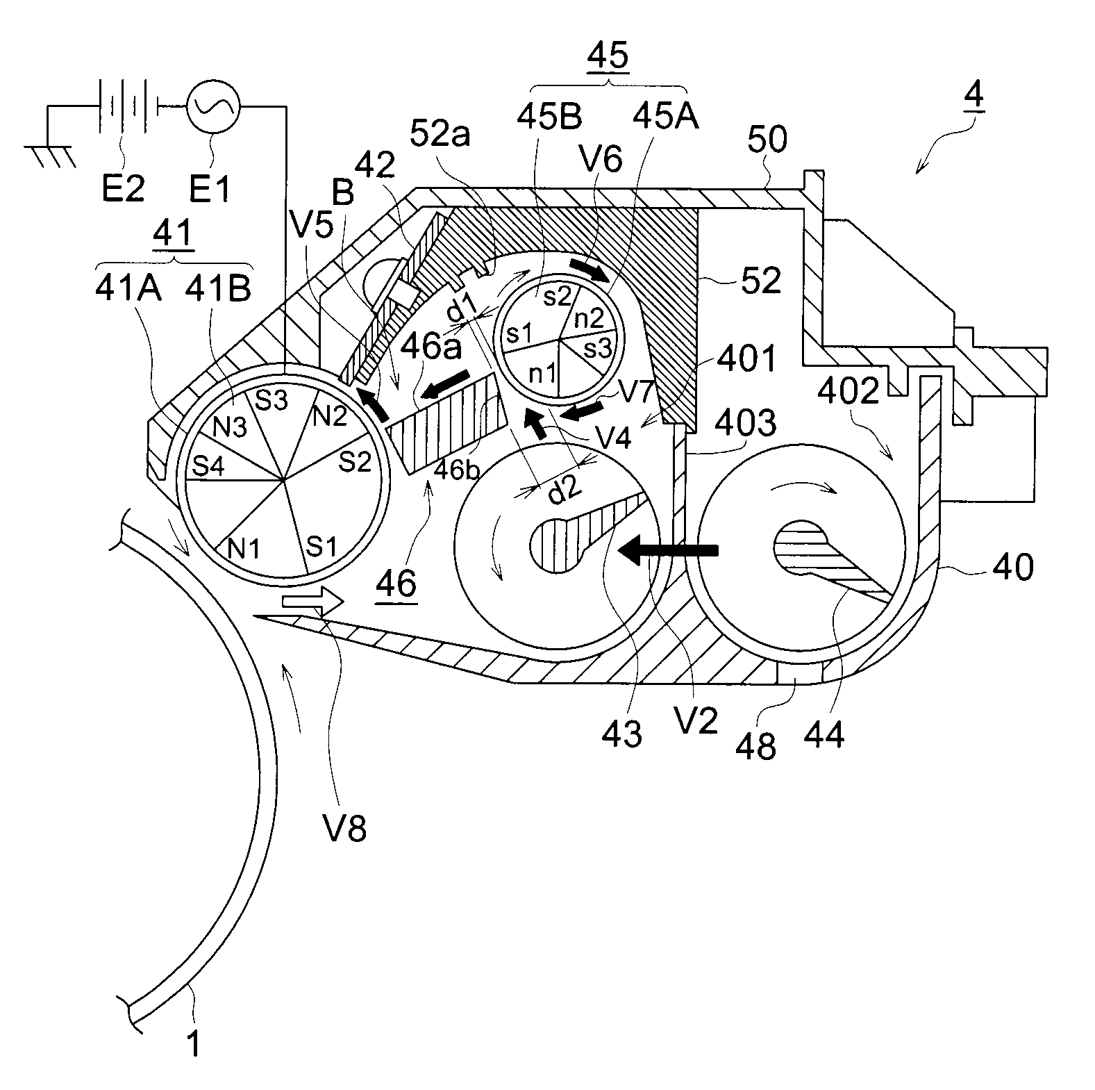
[0134][Developing Device] (Refer to FIG. 1)

[0135]Developer feed roller 45: having a sleeve 45A and a magnet roll 45B

[0136]Sleeve 45A: external diameter 16 mm, clockwise rotating

[0137]Magnet roll 45B: having n1, n2, s1, s2, and s3 poles totaling to 5 magnetic poles

[0138]The incline angle of each magnetic pole is expressed in such a manner that a straight line extending upward vertically from the rotational axis center of the magnet roll 45B is designated as a base angle of 0° and an angle created when clockwise rotation is made is expressed as the inclined angle of the each magnetic pole.

[0139]s2 pole: inclined angle 20°, magnetic flux density 50 mT (mTesla)

[0140]n2 pole: inclined angle 80°, magnetic flux density 60 mT

[0141]s3 pole: inclined angle 130°, magnetic flux density 50 mT

[0142]n1 pole: inclined angle 180°, magnetic flux density 60 mT

[0143]s1 pole: inclined angle 265°, magnetic flux density 20 mT

[0144]The inclined angle of the s2 pole is preferably set at a value between 10°-...

example 2

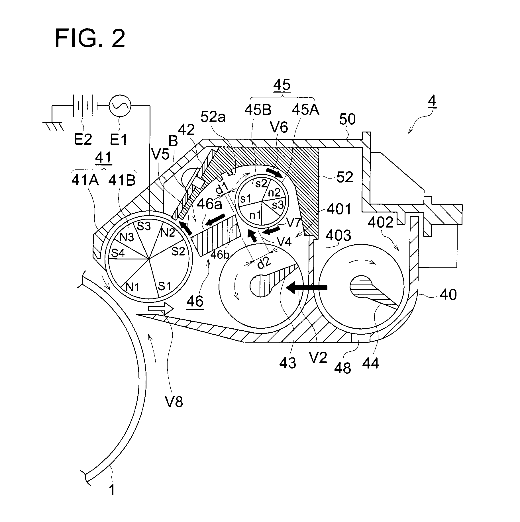
[0147][Developing Device] (Refer to FIG. 5)

[0148]Developer feed roller 45: having a sleeve 45A and a magnet roll 45B

[0149]Sleeve 45A: external diameter 16 mm, clockwise rotating

[0150]Magnet roll 45B: having n1, n2, s1, and s2 poles totaling to 4 magnetic poles

[0151]The incline angle of each magnetic pole is expressed in such a manner that a straight line extending upward vertically from the rotational axis center of the magnet roll 45B is designated as a base angle of 0° and an angle created when clockwise rotation is made is expressed as the inclined angle of the each magnetic pole.

[0152]s2 pole: inclined angle 20°, magnetic flux density 60 mT (mTesla)

[0153]n2 pole: inclined angle 100°, magnetic flux density 20 mT

[0154]n1 pole: inclined angle 180°, magnetic flux density 60 mT

[0155]s1 pole: inclined angle 265°, magnetic flux density 20 mT

[0156]The inclined angle of the s2 pole is preferably set at a value between 10°-30°. When the angle is set at less than 10°, the amount of the dev...


PUM


Abstract

Provided is a developing device which can prevent the occurrence of a phenomenon of an excessive increase of a developer quantity in a developer standby space, thereby acquiring a stable image. The developing device comprises a developer agitation-transfer unit, a developer roller, a developer feeding roller, a developer guide member and a space forming member. The developing device is characterized in that the developer feeding roller rotates to transfer the developer transferred by the agitation-transfer means, upward from the clearance between the developer feeding roller and the developer guide member, and in that, when the developer standby space formed in the device is filled with the developer transferred by the developer feeding roller, the developer feeding roller is rotated to carry the developer, which overflows from the developer standby space, and to move the same in the direction away from the developer roller, so that the developer is once discharged from the developer standby space.

Description

CROSS REFERENCE TO RELATED APPLICATIONS[0001]This application is a national phase application based on International Application No. PCT / JP2009 / 062961, filed Jul. 17, 2009, which claims the priority of Japanese Patent Application No. 2008-205267, filed Aug. 8, 2008, the content of both of which is incorporated herein by reference.TECHNICAL FIELD[0002]The present invention relates to a developing device, which develops an electrostatic latent image formed on an image carrier, used for copiers, printers, facsimile machines, or image forming apparatuses with multifunction employing an electrophotographic technology.BACKGROUND[0003]Conventionally, there has existed a developing device mainly incorporating a developing roller and a plurality of stirring and conveying screws. A developing device with this constitution produces the advantage of realization of size reduction. However, this developing device is inadequate in terms of uniform stirring of a developer, producing then such a dis...

Claims


Application Information

Patent Timeline
Patent Type & Authority Patents(United States)
IPC IPC(8): G03G15/08
CPCG03G15/0808G03G15/081G03G2215/0822G03G2215/0838
Inventor ITAGAKI, SEIKOAKITA, HIROSHIMINEGISHI, NATSUKO
Owner KONICA MINOLTA BUSINESS TECH INC
Why Eureka
Try Eureka