PWM generating unit, image forming apparatus, and image forming method
- Summary
- Abstract
- Description
- Claims
- Application Information
AI Technical Summary
Benefits of technology
Problems solved by technology
Method used
Image
Examples
first embodiment
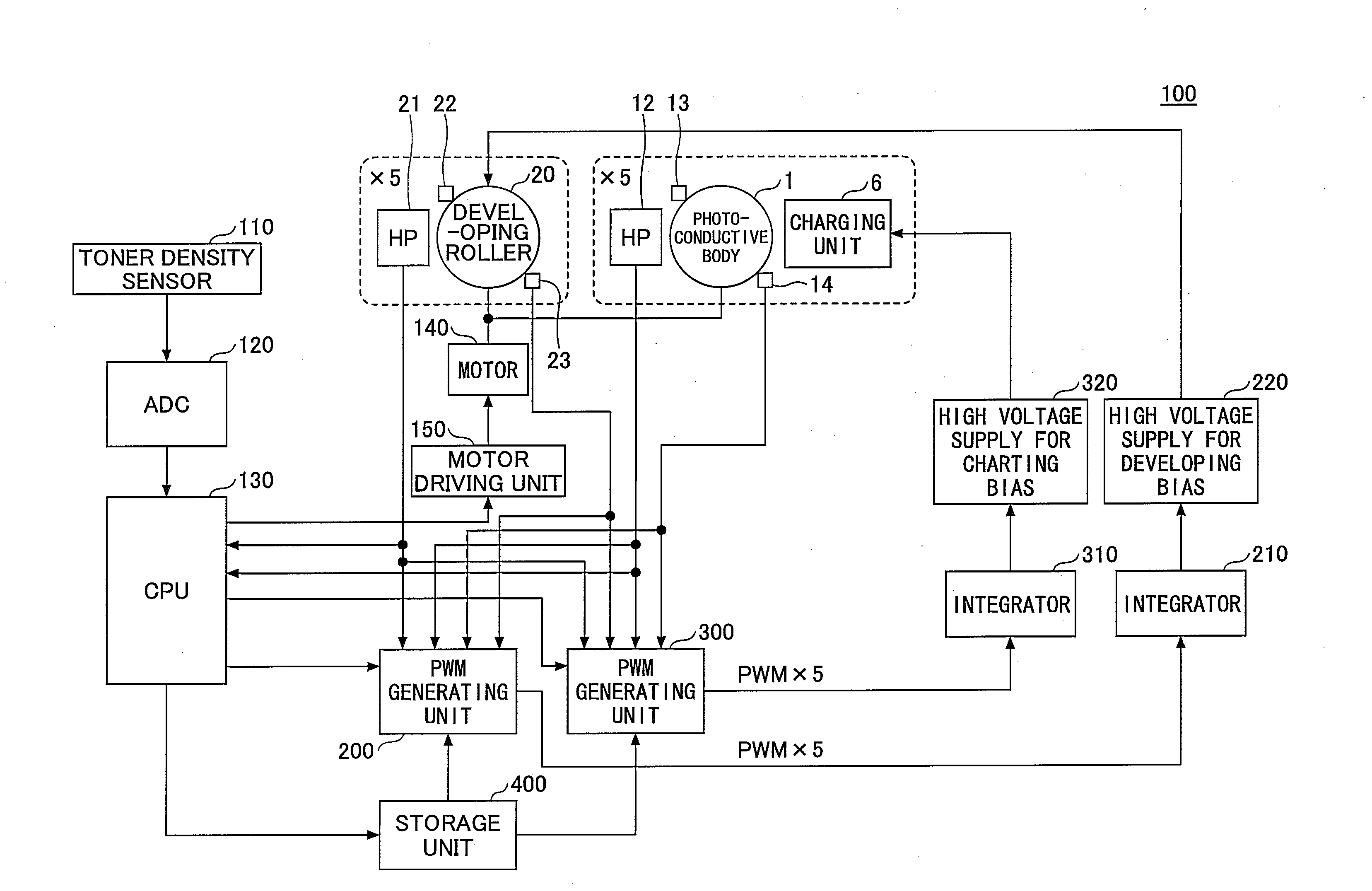
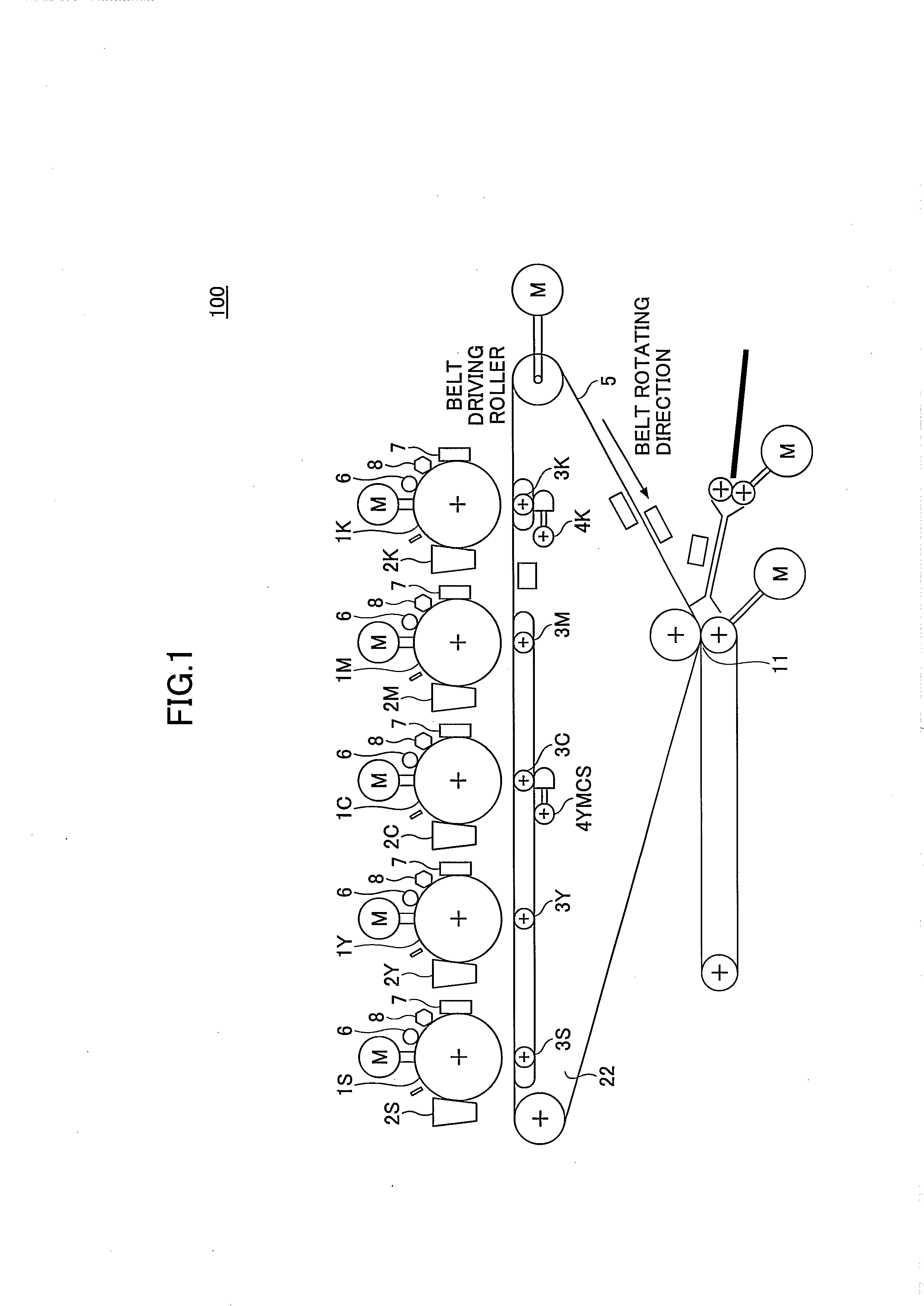
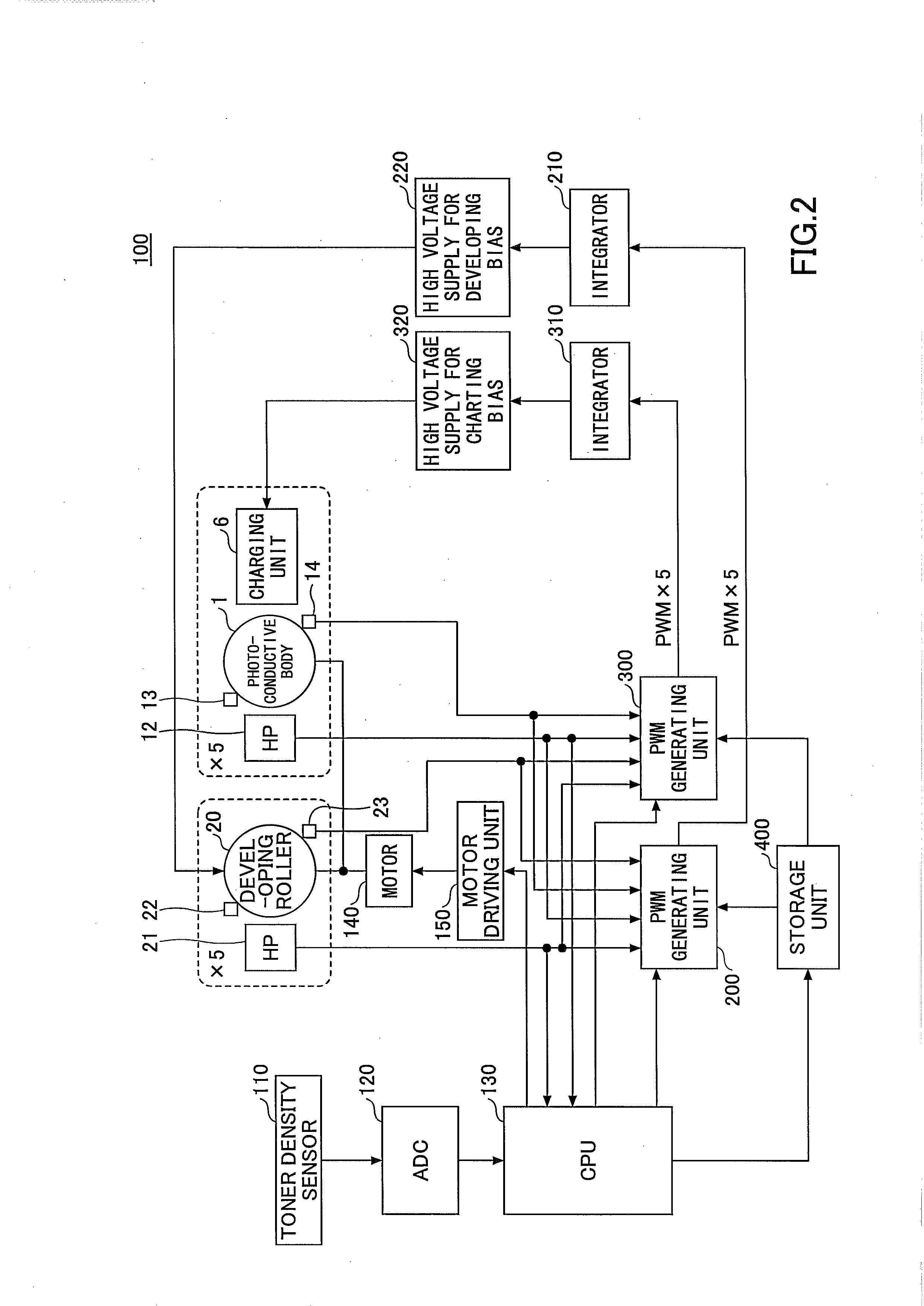
[0031]A description will be given of a first embodiment of the present invention. FIG. 1 is a diagram schematically illustrating functions related to an image formation in the image forming apparatus in the first embodiment.
[0032]An image forming apparatus 100 in this first embodiment may include a plurality of photoconductive bodies 1Y, 1C, 1M, 1K, and 1S (each hereinafter simply referred to as a “photoconductive body 1” when not referring to a specific photoconductive body). The photoconductive body 1 is an example of a first rotational body. Developing units 2Y, 2C, 2M, 2K, and 2S (each hereinafter simply referred to as a “developing unit 2” when not referring to a specific developing unit), and transfer units 3Y, 3C, 3M, 3K, and 3S (each hereinafter simply referred to as a “transfer unit 3” when not referring to a specific transfer unit) are respectively provided with respect to each photoconductive body 1. In the image forming apparatus 100, each photoconductive body 1 is unifo...
second embodiment
[0131]Next, a description will be given of a second embodiment of the present invention, by referring to FIG. 13. FIG. 13 is a diagram for explaining the PWM generator in the second embodiment.
[0132]This second embodiment differs from the first embodiment in that the rotation period of the photoconductive body 1, the rotation period of the developing roller 20, the correction data for correcting the rotation period of the photoconductive body 1, and the correction data for correcting the rotation period of the developing roller 20 are approximated by first order components and second order components of the sinusoidal wave. Otherwise, this second embodiment is similar to the first embodiment. In FIG. 13, those parts that have the same function as the corresponding parts of the first embodiment illustrated in FIG. 10 are designated by the same reference numerals, and a description thereof will be omitted.
[0133]A PWM generating unit 200A illustrated in FIG. 13 may output a PWM signal ...
third embodiment
[0147]Next, a description will be given of a third embodiment of the present invention, by referring to FIG. 14. FIG. 14 is a diagram illustrating an example of a system structure of the image forming system in the third embodiment. In FIG. 14, those parts that have the same function as the corresponding parts of the first embodiment are designated by the same reference numerals, and a description thereof will be omitted. In this embodiment, the present invention is applied to an image forming system that stores the correction data in an external apparatus.
[0148]In this embodiment, an image forming system 500 may include the image forming apparatus 100 and a server 600 that are connected via suitable interface units. The server 600 may be connected to PCs (Personal Computers) P1, P2, . . . , and PN via a network N.
[0149]In this embodiment, the correction data computed by a CPU 130 of the image forming apparatus 100 may be stored in the server 600. The server 600 may include a commun...
PUM
 Abstract
Description
Claims
Application Information
 - R&D
- Intellectual Property
- Life Sciences
- Materials
- Tech Scout
- Unparalleled Data Quality
- Higher Quality Content
- 60% Fewer Hallucinations
Browse by: Latest US Patents, China's latest patents, Technical Efficacy Thesaurus, Application Domain, Technology Topic, Popular Technical Reports.
© 2025 PatSnap. All rights reserved.Legal|Privacy policy|Modern Slavery Act Transparency Statement|Sitemap|About US| Contact US: help@patsnap.com


