PWM generating unit, image forming apparatus, and image forming method

a technology of generating unit and forming apparatus, which is applied in the direction of process and machine control, instruments, and corona discharge, can solve the problems of increasing the processing load on the cpu, and achieve the effect of reducing processing load and correcting density non-uniformity

Inactive Publication Date: 2014-11-11
RICOH KK
View PDF12 Cites 1 Cited by
  • Summary
  • Abstract
  • Description
  • Claims
  • Application Information

AI Technical Summary

Benefits of technology

[0011]Another and more specific object in one embodiment of the present invention is to provide a PWM generating unit, an image forming apparatus, an image forming method, and an image forming system, which may correct the density non-uniformity with a reduced processing load.

Problems solved by technology

However, the prior art may store density variation data for every image forming condition in a storage unit, for example, and correct the density non-uniformity using the stored density variation data.
Consequently, a processing load on the CPU increases, and in some cases, a dedicated CPU may be required exclusively for the correction of the density non-uniformity.

Method used


Image

  • PWM generating unit, image forming apparatus, and image forming method
  • PWM generating unit, image forming apparatus, and image forming method
  • PWM generating unit, image forming apparatus, and image forming method

Examples


first embodiment

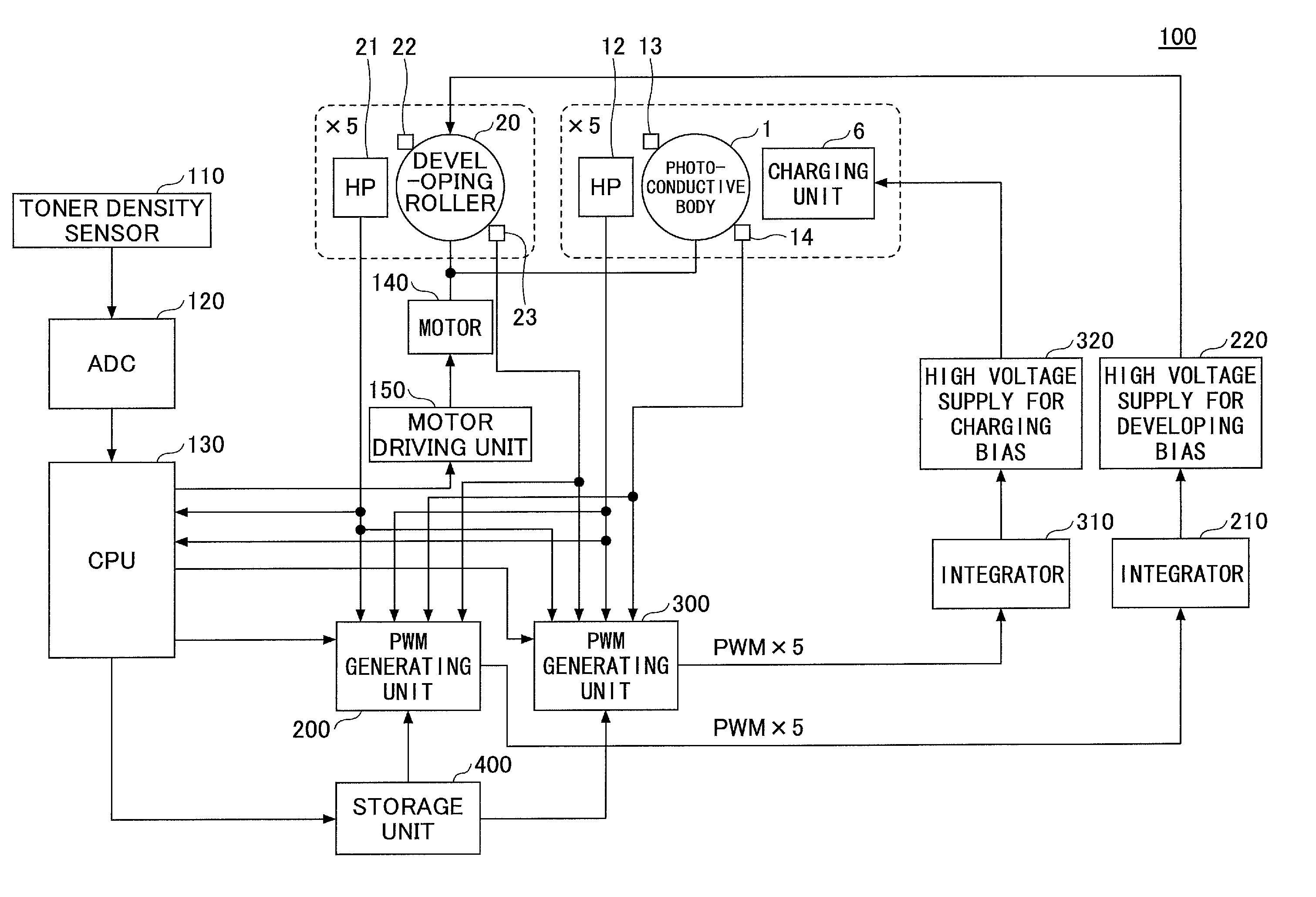
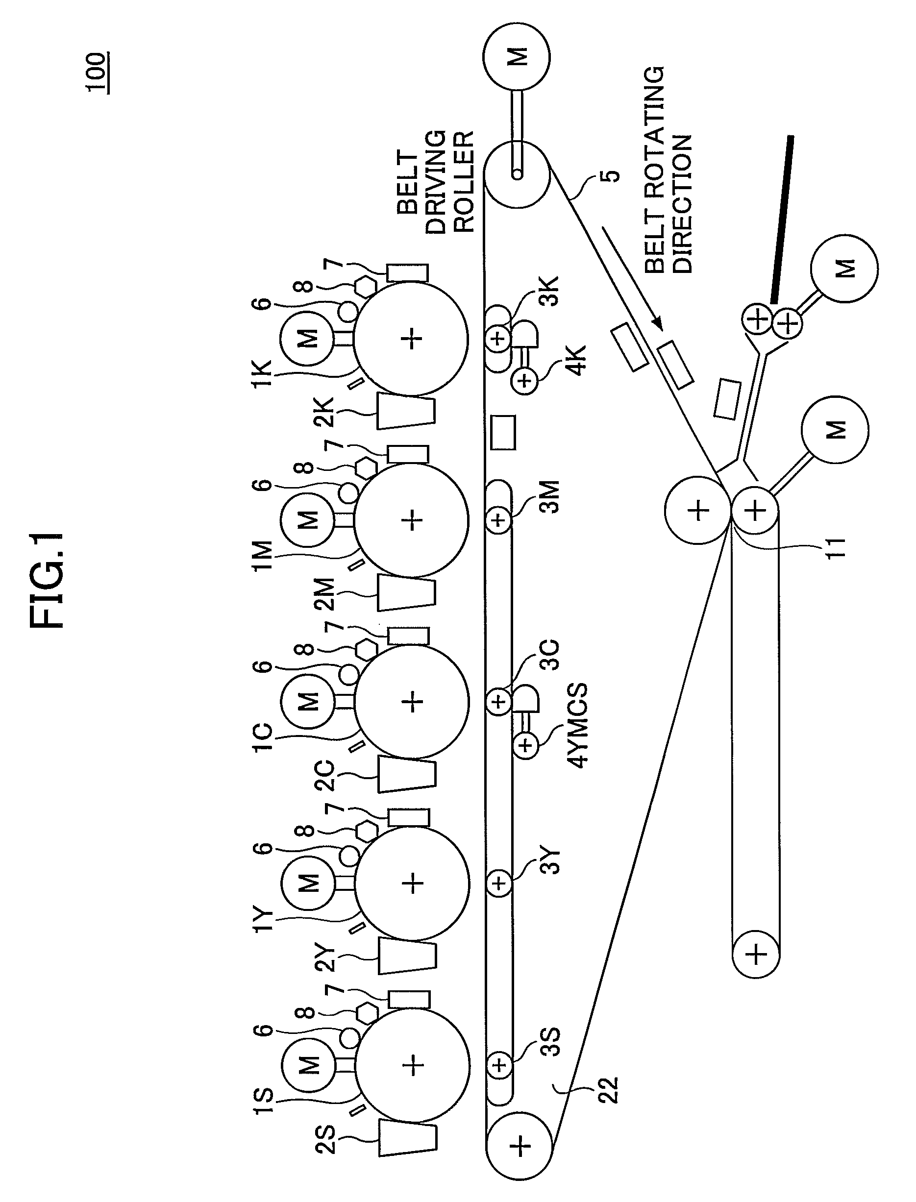
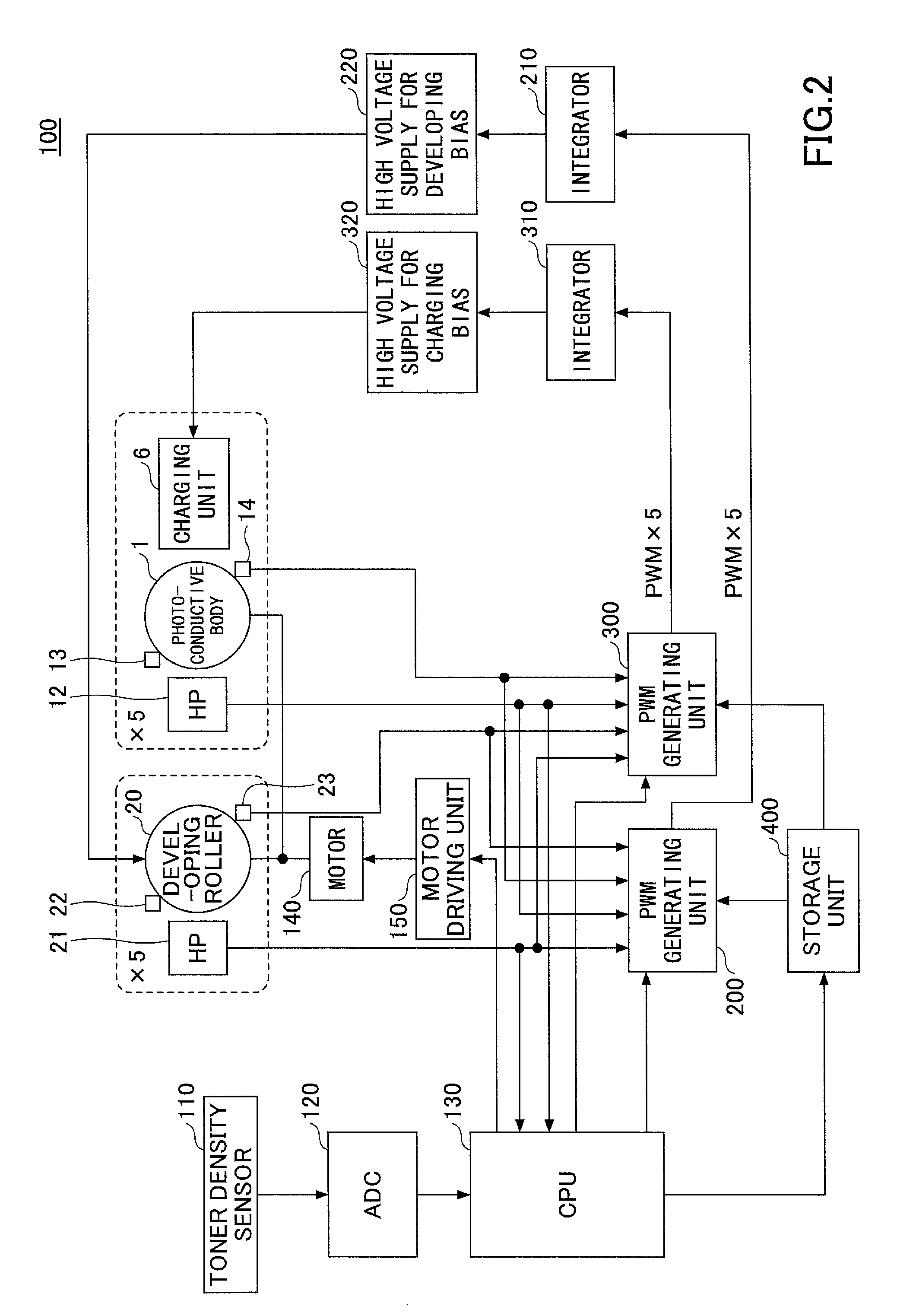
[0031]A description will be given of a first embodiment of the present invention. FIG. 1 is a diagram schematically illustrating functions related to an image formation in the image forming apparatus in the first embodiment.

[0032]An image forming apparatus 100 in this first embodiment may include a plurality of photoconductive bodies 1Y, 1C, 1M, 1K, and 1S (each hereinafter simply referred to as a “photoconductive body 1” when not referring to a specific photoconductive body). The photoconductive body 1 is an example of a first rotational body. Developing units 2Y, 2C, 2M, 2K, and 2S (each hereinafter simply referred to as a “developing unit 2” when not referring to a specific developing unit), and transfer units 3Y, 3C, 3M, 3K, and 3S (each hereinafter simply referred to as a “transfer unit 3” when not referring to a specific transfer unit) are respectively provided with respect to each photoconductive body 1. In the image forming apparatus 100, each photoconductive body 1 is unifo...

second embodiment

[0135]Next, a description will be given of a second embodiment of the present invention, by referring to FIG. 13. FIG. 13 is a diagram for explaining the PWM generator in the second embodiment.

[0136]This second embodiment differs from the first embodiment in that the rotation period of the photoconductive body 1, the rotation period of the developing roller 20, the correction data for correcting the rotation period of the photoconductive body 1, and the correction data for correcting the rotation period of the developing roller 20 are approximated by first order components and second order components of the sinusoidal wave. Otherwise, this second embodiment is similar to the first embodiment. In FIG. 13, those parts that have the same function as the corresponding parts of the first embodiment illustrated in FIG. 10 are designated by the same reference numerals, and a description thereof will be omitted.

[0137]A PWM generating unit 200A illustrated in FIG. 13 may output a PWM signal ...

third embodiment

[0152]Next, a description will be given of a third embodiment of the present invention, by referring to FIG. 14. FIG. 14 is a diagram illustrating an example of a system structure of the image forming system in the third embodiment. In FIG. 14, those parts that have the same function as the corresponding parts of the first embodiment are designated by the same reference numerals, and a description thereof will be omitted. In this embodiment, the present invention is applied to an image forming system that stores the correction data in an external apparatus.

[0153]In this embodiment, an image forming system 500 may include the image forming apparatus 100 and a server 600 that are connected via suitable interface units. The server 600 may be connected to PCs (Personal Computers) P1, P2, . . . , and PN via a network N.

[0154]In this embodiment, the correction data computed by a CPU 130 of the image forming apparatus 100 may be stored in the server 600. The server 600 may include a commun...


PUM


Abstract

A PWM generating unit may include a base duty setting register configured to store a base duty value that is set thereto, and a PWM generator to obtain a corrected duty value by correcting the base duty value based on first correction data and second correction data, and to generate a PWM signal according to the corrected duty value. The first correction data may be computed from a rotation period of a first rotational body, and the second correction data may be computed from a rotation period of a second rotational body.

Description

CROSS-REFERENCE TO RELATED APPLICATIONS[0001]This application is based upon and claims the benefit of priority of the prior Japanese Patent Application No. 2012-002571, filed on Jan. 10, 2012, the entire contents of which are incorporated herein by reference.BACKGROUND OF THE INVENTION[0002]1. Field of the Invention[0003]The present invention relates to a PWM generating unit for generating a PWM (Pulse Width Modulation) signal according to a duty value, an image forming apparatus, an image forming method, and an image forming system.[0004]2. Description of the Related Art[0005]In a prior art image forming apparatus using the electrophotography method, a toner image is adhered on a photoconductive body by utilizing an electric field caused by a potential difference between a developing roller and the photoconductive body. It is generally known that this electric field varies depending on a developing gap, that is, the distance between the photoconductive body and the developing rolle...

Claims


Application Information

Patent Timeline
Patent Type & Authority Patents(United States)
IPC IPC(8): G03G15/00G03G15/06G03G15/02
CPCG03G15/065G03G15/5004
Inventor IWASAKI, HIROYUKI
Owner RICOH KK
Why Eureka
Try Eureka