Vehicle body frame structure

a frame structure and vehicle technology, applied in the direction of roofs, bumpers, vehicle components, etc., can solve the problems of difficult to absorb impact load, front side frame, and inefficient transmission of impact load to impact absorption member, so as to reduce transmit impact load efficiently, and restrict local bending of the bumper beam

Active Publication Date: 2015-06-16
HONDA MOTOR CO LTD
View PDF28 Cites 18 Cited by
  • Summary
  • Abstract
  • Description
  • Claims
  • Application Information

AI Technical Summary

Benefits of technology

[0016]According to the aspect of the above (1), when an impact load at the time of a narrow offset collision is input to an outer portion of the bumper beam which is the portion positioned more outward in the vehicle width direction than the side frame, the outer portion of the bumper beam bends inwardly in the vehicle body front-rear direction such that a connection portion between the bumper beam and the impact absorption member is a fulcrum.
[0017]Thereby, the bumper beam and the fit member relatively approach each other, the bumper beam overlaps the fit member from the outside in the vehicle body front-rear direction, and thereby the fit member fits the inside of the bumper beam. As a result, bending of the bumper beam is restricted, and the impact load is absorbed by the subframe through the fit member.
[0018]On the other hand, when bending of the bumper beam is restricted, part of the impact load is transmitted toward the central portion in the vehicle width direction of the bumper beam and is transmitted to the impact absorption member.
[0019]Thereby, the impact absorption member is deformed. Thus, the impact load is absorbed, and the connection portion of the bumper beam with the impact absorption member moves inwardly in the vehicle body front-rear direction. In other words, the overall outer portion of the bumper beam moves inwardly in the vehicle body front-rear direction and fits the fit member, and the remaining impact load of the impact load is absorbed by the side frame through the fit member.
[0020]According to the configuration above, the bumper beam and the fit member are configured to be capable of fitting to each other when an impact load is input, and therefore it is possible to restrict local bending of the bumper beam and to transmit the impact load efficiently toward the impact absorption member, the side frame, the subframe, and the like. Accordingly, it is possible to absorb the impact load efficiently even at the time of a narrow offset collision.
[0021]In addition, since the configuration is a simple configuration in which the bumper beam having a concave shape and the protrusive fit member are configured to be capable of fitting to each other, it is possible to achieve cost reduction and weight saving in comparison with a configuration of the related art in which a diagonal beam is provided on a front side frame that is a skeletal member, a configuration of the related art in which a bumper beam having a closed cross-sectional structure is adopted, or the like.

Problems solved by technology

However, at the time of a front collision, when an impact load is input to an outer portion of the bumper beam which is the portion positioned more outward in the vehicle width direction than the front side frames (when a so-called narrow offset collision occurs), there may be a case where a local bending of only the outer portion just occurs, an impact load does not efficiently transmit to the impact absorption member, the front side frame, and the like, and the impact load is difficult to be absorbed.

Method used


Image

  • Vehicle body frame structure
  • Vehicle body frame structure
  • Vehicle body frame structure

Examples


Embodiment Construction

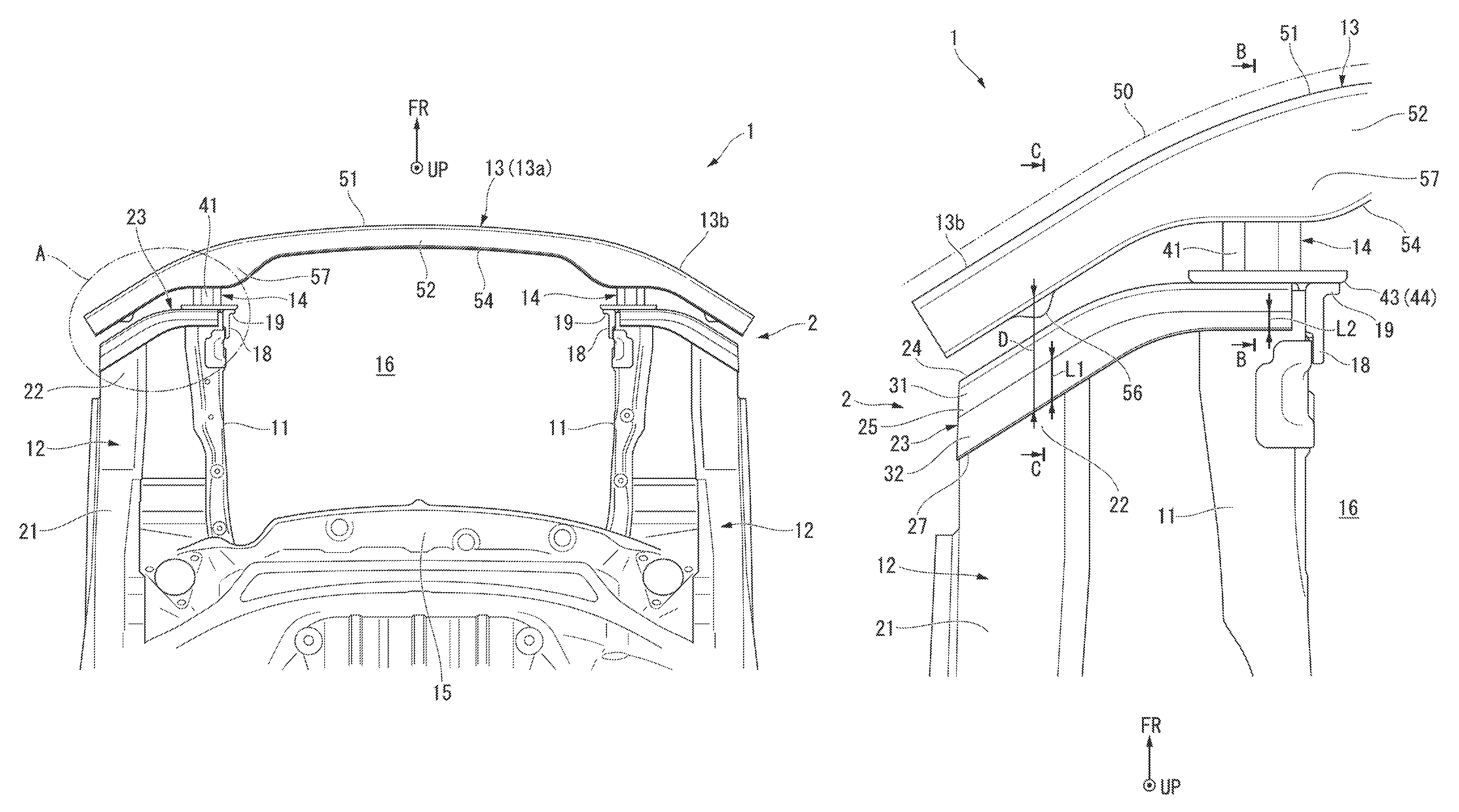
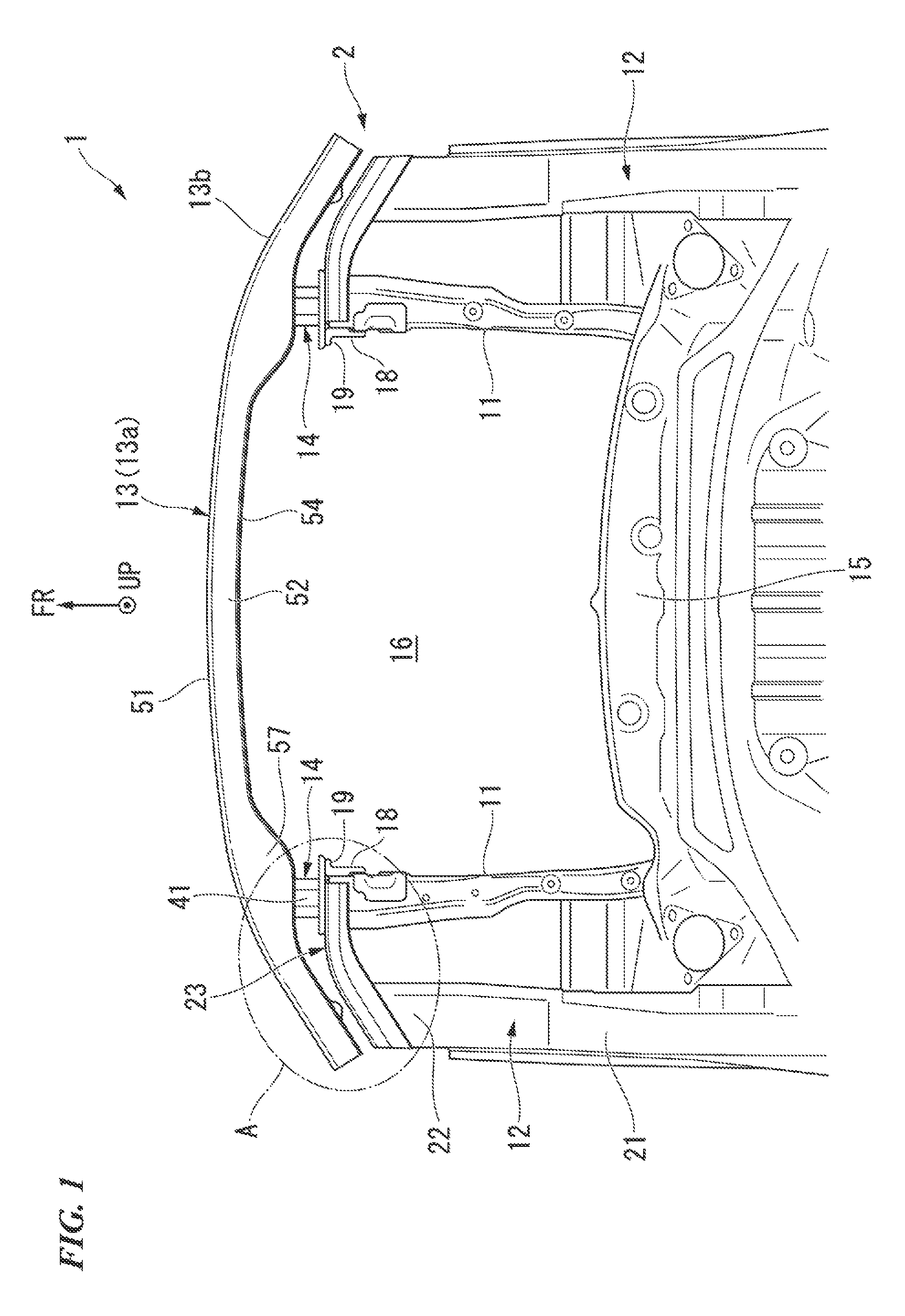
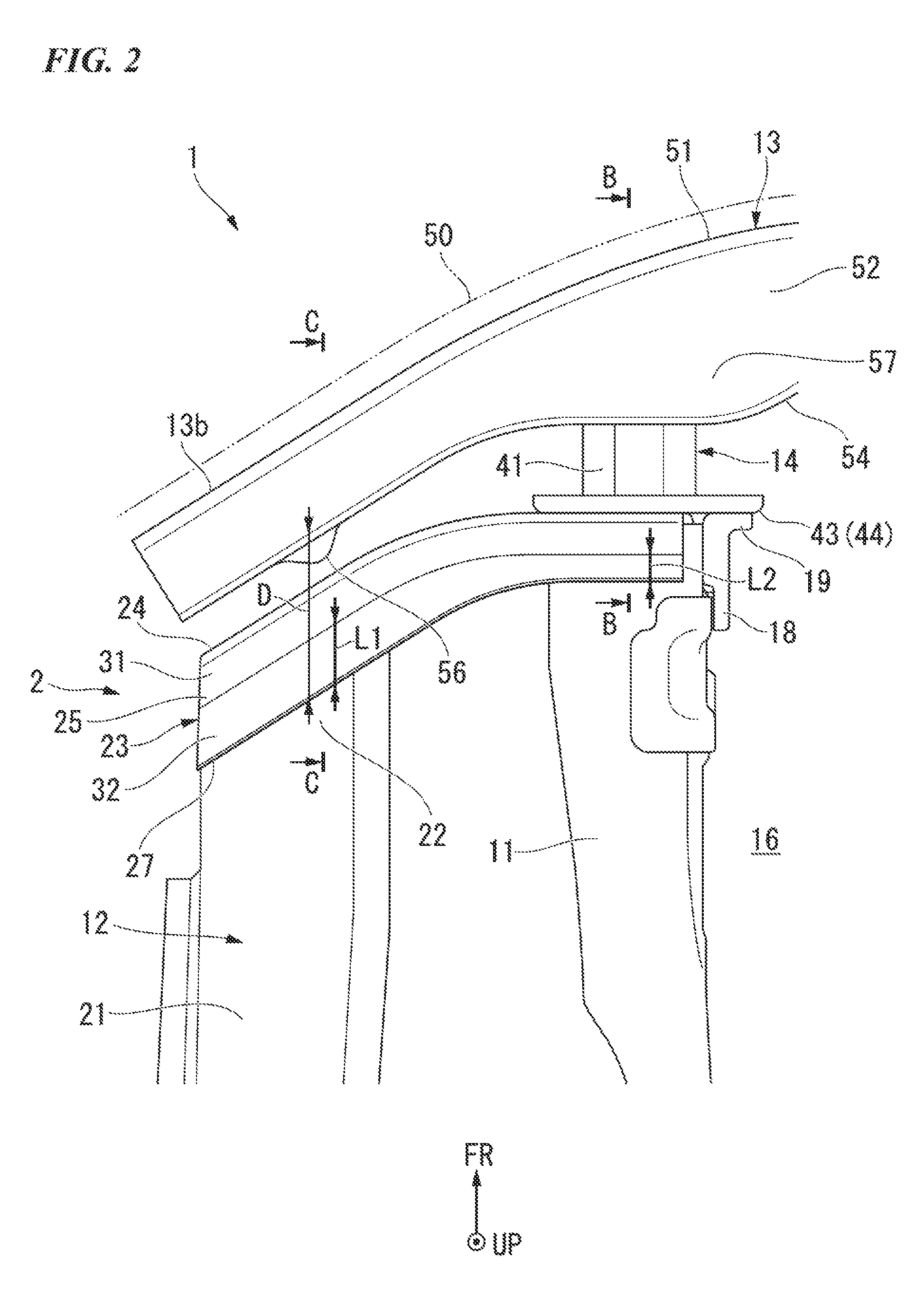
[0053]Next, an embodiment of the present invention will be described based on the drawings. The present embodiment is described using an example in which a vehicle body frame structure of the present invention is applied to a front portion structure of a vehicle body. Note that, it is supposed that directions, such as front, rear, up, down, right, and left in the following description are the same as directions in a vehicle if there is no particular description. In addition, in the drawings, an arrow FR indicates the front of the vehicle (the outside in the vehicle body front-rear direction), and an arrow UP indicates the upper side of the vehicle. FIG. 1 is a plan view showing a vehicle body front portion according to the present embodiment, and FIG. 2 is an enlarged plan view of an A portion of FIG. 1.

[0054]As shown in FIG. 1 and FIG. 2, a front portion structure (vehicle body frame structure) 2 of a vehicle body 1 according to the present embodiment includes: a pair of front side...


PUM


Abstract

A front portion structure (2) of a vehicle body (1) includes: a pair of front side frames (11) that extend along a vehicle body front-rear direction on both sides in a vehicle width direction; a lower member (12) that extends along the vehicle body front-rear direction on the outside in the vehicle width direction of the front side frame (11); a bumper beam (13) provided in the front of the front side frame (11) and extending along the vehicle width direction; a bumper beam extension (14) provided between the front side frame (11) and the bumper beam (13); and a gusset (23) that connects a front end portion of the front side frame (11) and a front end portion of the lower member (12) and that is formed in a protrusion protruding forwardly, wherein the bumper beam (13) is configured to have a concave shape opening rearwardly and to be capable of fitting the gusset (23).

Description

TECHNICAL FIELD[0001]The present invention relates to a vehicle body frame structure.[0002]Priority is claimed on Japanese Patent Application No. 2012-123974 filed on May 31, 2012, the contents of which are incorporated herein by reference.BACKGROUND[0003]In the related art, for example, as a vehicle body front portion structure (vehicle body frame structure) used to absorb an impact from the vehicle front, a configuration is known which includes front side frames that extend along the front-rear direction on both sides in the vehicle width direction and a bumper beam that extends along the vehicle width direction in the front of the front side frames, and in which an impact absorption member connects a front end portion of the front side frames and the bumper beam.[0004]According to this configuration, at the time of a vehicle front crash (hereinafter, referred to as a front collision), when an impact load is input from the vehicle front (bumper beam side), the impact load is absor...

Claims


Application Information

Patent Timeline
Patent Type & Authority Patents(United States)
IPC IPC(8): B60J7/00B62D21/15B60R19/24B60R19/34B60R19/18
CPCB62D21/152B60R19/24B60R19/34B60R19/18B60R2019/1806
Inventor WATANABE, YASUNORI
Owner HONDA MOTOR CO LTD
Why Eureka
Try Eureka