Supercharge Your Innovation With Domain-Expert AI Agents!

Mud motor

a technology of motors and mud, applied in the direction of machines/engines, mechanical devices, couplings, etc., can solve the problems of seal leakage, premature failure of bearing assemblies, pressure drop between upper and lower seals of bearing assemblies, etc., and achieve the effect of facilitating the rotation of the passageway

Active Publication Date: 2015-06-16
THRU TUBING SOLUTIONS
View PDF12 Cites 2 Cited by
  • Summary
  • Abstract
  • Description
  • Claims
  • Application Information

AI Technical Summary

Benefits of technology

The present invention relates to a pressure balanced mud motor, which is used in drilling oil wells. The motor includes a power section, a passageway housing, a bearing assembly, and a hydraulic apparatus to balance pressure drops. The motor also includes a roller bearing with a roller cage and a retaining ring. The invention maintains a balanced pressure across the bearing assembly and uses a special method to deploy the motor into a wellbore. The technical effects of the invention include improved drilling efficiency, reduced wear and tear of equipment, and improved safety during drilling operations.

Problems solved by technology

As fluid flows through the sealed mud motor and across the seals and bearing assemblies, a pressure drop occurs between upper and lower seals associated with the bearing assemblies due to the friction loss associated with fluid flowing through the sealed mud motor.
This pressure drop can cause the seals to leak, allowing drilling fluid to enter the bearing assemblies and cause premature failure of the bearing assemblies.

Method used


Image

  • Mud motor
  • Mud motor
  • Mud motor

Examples


Embodiment Construction

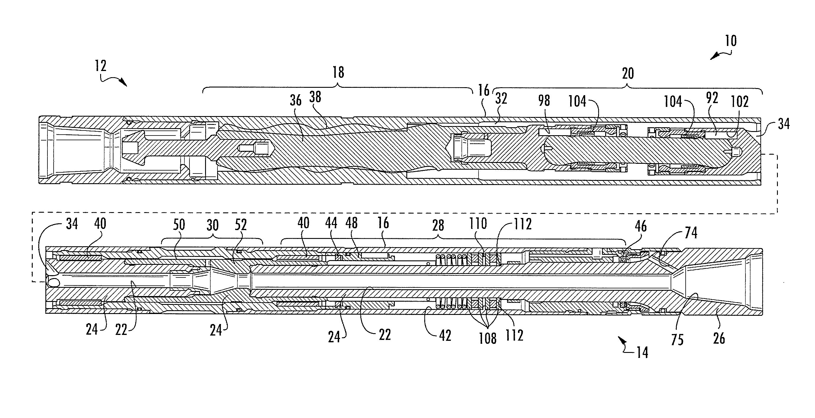
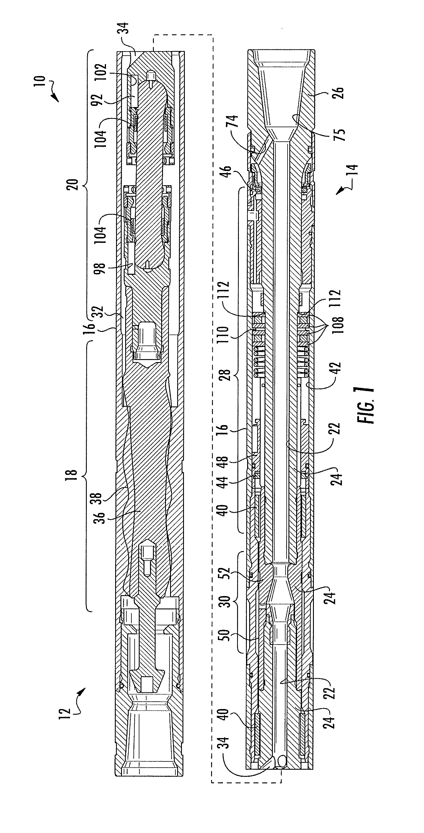
[0020]The present disclosure relates to a mud motor 10 used in downhole oil and gas operations that substantially reduces a pressure drop (or pressure differential) across the portions of the mud motor 10 caused by the friction of fluid (e.g., mud, drilling fluid, drilling mud, etc.) flowing therethrough. The present disclosure is also directed to a method of using this mud motor while maintaining a substantially balanced pressure drop across various portions of the mud motor. Shown in FIG. 1, the mud motor 10 includes an upper portion 12, a lower portion 14 and a housing 16 for encapsulating various parts of the mud motor 10.

[0021]The upper portion 12 includes a power section 18 for driving / forcing the fluid through the mud motor 10 and rotating the various parts of the mud motor 10 encapsulated in the housing 16 and a drive shaft assembly 20 for transferring the rotation produced by the power section 18 to other components disposed in the lower portion 14 of the mud motor 10.

[0022...


PUM


Abstract

This application is directed to a pressure balanced mud motor and a method of using the mud motor. The mud motor includes a power section to rotate a passageway housing and propel fluid through a passageway disposed in the passageway housing. The mud motor also includes a hydraulic apparatus for balancing a pressure drop experienced across a bearing assembly due to frictional flow of fluid through the passageway.

Description

CROSS-REFERENCE TO RELATED APPLICATIONS[0001]The present application is a divisional of U.S. patent application having U.S. Ser. No. 14 / 104,276, filed Dec. 12, 2013, which claims the benefit under 35 U.S.C. 119(e). The disclosure of which is hereby expressly incorporated herein by reference.STATEMENT REGARDING FEDERALLY SPONSORED RESEARCH OR DEVELOPMENT[0002]Not applicable.BACKGROUND OF THE DISCLOSURE[0003]1. Field of the Invention[0004]The present invention relates to a mud motor used in oil and gas operations that is pressure balanced.[0005]2. Description of the Related Art[0006]Standard sealed mud motors typically have radial bearings / assemblies that are exposed to well bore fluids. The fluid that operates the sealed mud motor must pass across the bearing assemblies and out of the sealed mud motor. Typically, the bearing assemblies have seals that prevent pumped fluid from contaminating any grease or oil used in the bearing assemblies. As fluid flows through the sealed mud motor ...

Claims


Application Information

Patent Timeline
Patent Type & Authority Patents(United States)
IPC IPC(8): E21B4/02E21B4/00E21B44/00F03B13/02
CPCE21B4/02E21B4/003F03B13/02E21B44/005F16C19/305F16D3/221F16D3/24
Inventor WATSON, BROCKKLIEWER, GREGORYSCHULTZ, ROGER L.
Owner THRU TUBING SOLUTIONS
Features
  • R&D
  • Intellectual Property
  • Life Sciences
  • Materials
  • Tech Scout
  • Unparalleled Data Quality
  • Higher Quality Content
  • 60% Fewer Hallucinations
Learn More