
Signal processor with an encrypting or decrypting device in a memory system

a memory system and sign processor technology, applied in the field of signal processors, can solve problems such as the decrease of the storage capacity of an area for storing data, and achieve the effect of minimizing the addition of resources and high security

Inactive Publication Date: 2015-06-16
MEGACHIPS
View PDF14 Cites 0 Cited by
  • Summary
  • Abstract
  • Description
  • Claims
  • Application Information

AI Technical Summary

Benefits of technology

[0006]It is an object of the present invention to provide a signal processor with high security by allowing the signal processor to process a plurality of key information items for encryption and decryption, while minimizing addition of a resource.
[0008]The original data which is a source for the key information is stored in the memory unit, and the key information generation unit variously modifies the original data which is read from the memory unit, to generate the plurality of key information items. Then, the processing unit encrypts each bit string with different key information. Consequently, since it is not required to store the plurality of key information items in the memory unit, it is possible to process the plurality of key information items, while minimizing addition of a resource, and security is improved.
[0010]The original data to be a source for the key information is stored in the memory unit, and the key information generation unit variously modifies the original data which is read from the memory unit, to generate the plurality of key information items. Then, the processing unit decrypts each encrypted bit string with different key information. Consequently, since it is not required to store the plurality of key information items in the memory unit, it is possible to process the plurality of key information items, while minimizing addition of a resource, and security is improved.
[0012]The key information generation unit produces the key information table in which the plurality of key information items is described, and stores this key information table in the buffer region. Consequently, changing the key information requires only selecting other key information from the key information table. Since there is no need to newly generate key information, processing speed can be enhanced.
[0014]The modifying unit of the key information generation unit modifies the parameter inputted from the processing unit to change the parameter to another parameter. Consequently, even if the parameter outputted from the processing unit gets cracked by a third party, the parameter is changed to another parameter by the modifying unit, and security is thus improved.
[0016]The modifying unit of the processing unit modifies the key information item inputted from the key information generation unit to change the key information to another key information item. Consequently, even if the key information outputted from the key information generation unit gets cracked by a third party, the key information is changed to other key information by the modifying unit, and security is thus improved.

Problems solved by technology

It causes an increase of an area to be secured for storing the data table in the memory cell array, and thus a decrease in storage capacity of an area for storing data.

Method used


Image

  • Signal processor with an encrypting or decrypting device in a memory system
  • Signal processor with an encrypting or decrypting device in a memory system
  • Signal processor with an encrypting or decrypting device in a memory system

Examples


first preferred embodiment

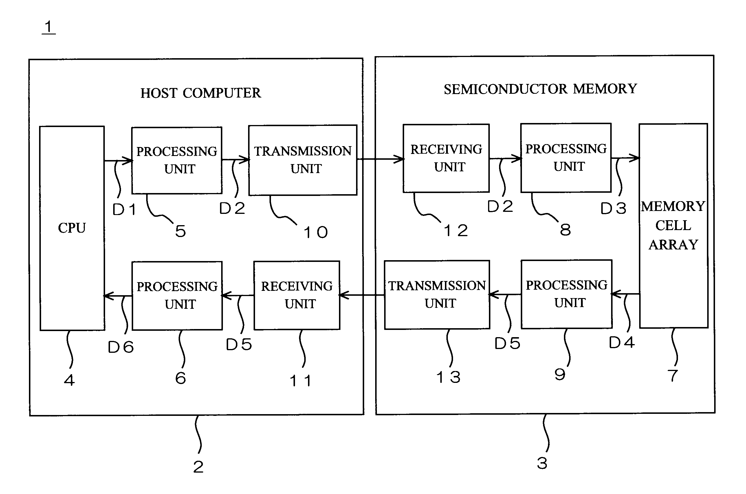
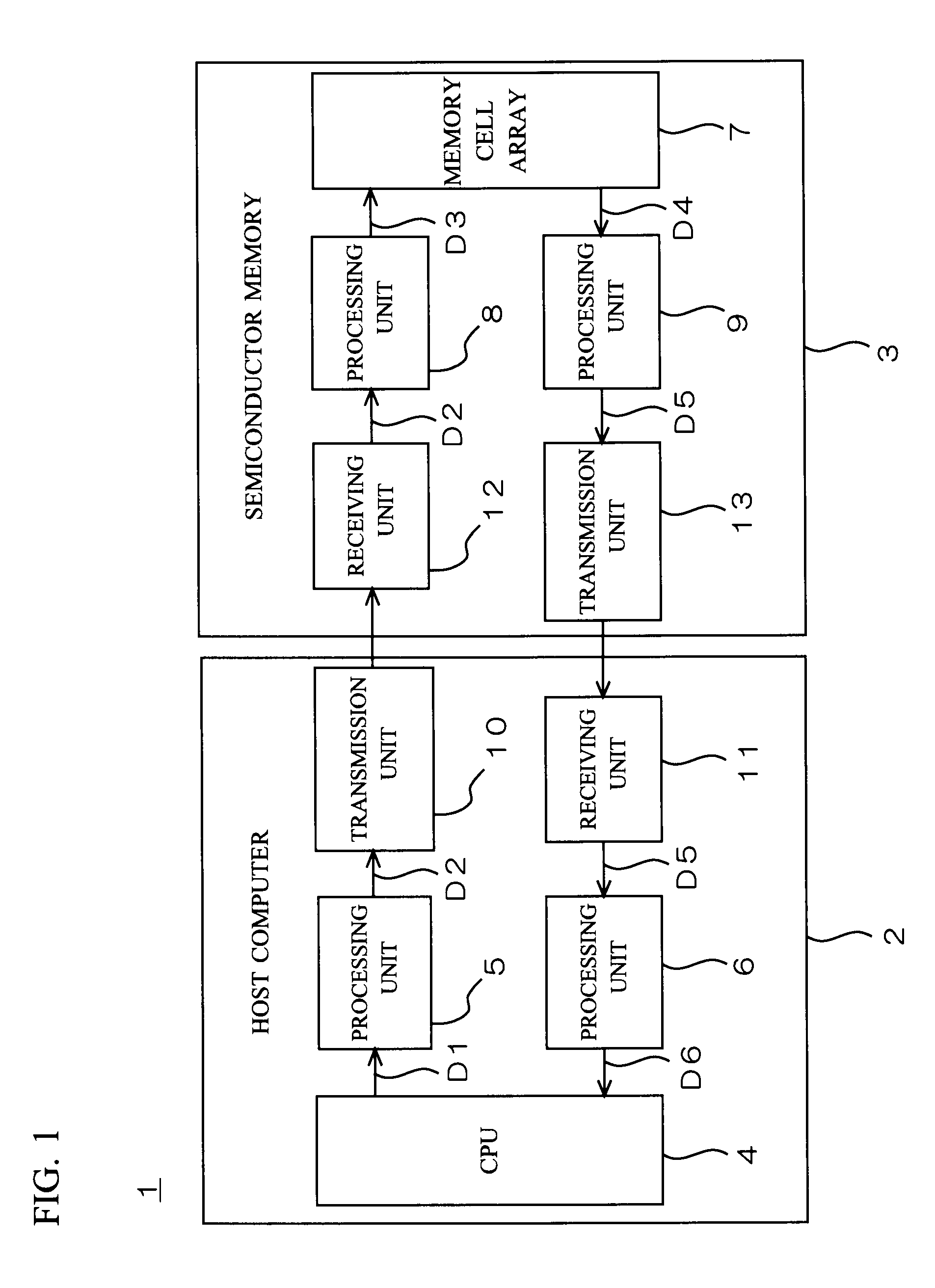
[0060]FIG. 1 is a block diagram showing an overall configuration of a signal processor 1 according to a first preferred embodiment of the present invention. The signal processor 1 includes a host computer 2 and a semiconductor memory 3. The semiconductor memory 3 is, for example, a memory card which is detachably connected to the host computer 2.

[0061]As shown in FIG. 1, the host computer 2 includes a CPU 4, processing units 5 and 6, a transmission unit 10, and a receiving unit 11. The semiconductor memory 3 includes a memory cell array 7, processing units 8 and 9, a receiving unit 12, and a transmission unit 13.

[0062]The present invention is illustrated below with an example of the host computer 2 reading data stored in the memory cell array 7. The present invention, however, is applicable not only to reading data from the memory cell array 7 but also to other processes such as writing data to the memory cell array 7.

[0063]Referring to FIG. 1, the CPU 4 outputs a command D1 for rea...

second preferred embodiment

[0112]FIG. 11 is a block diagram showing a configuration of a processing unit 5 shown in FIG. 1 of the signal processor 1 according to a second preferred embodiment of the present invention. The processing unit 5 includes a buffer region 54 which is referred to by an encryption unit 53, in addition to the buffer region 51, encryption key generation unit 52, and encryption unit 53, which are the elements same as those in the first preferred embodiment shown in FIG. 2.

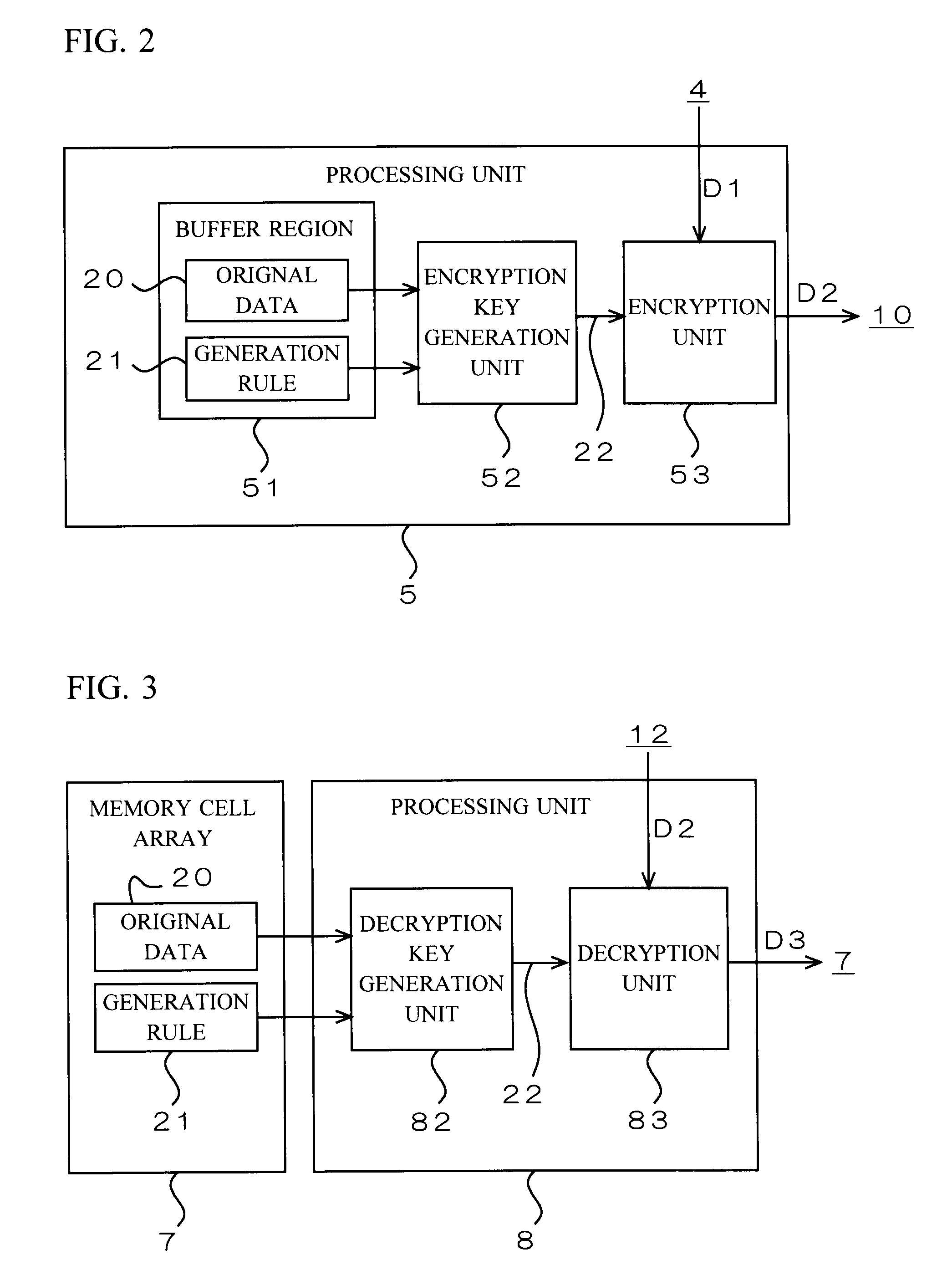
[0113]Immediately after the signal processor 1 is turned on, the encryption key generation unit 52 reads original data 20 and a generation rule 21 from the buffer region 51, and modifies the original data 20 variously based on the generation rule 21 to generate a plurality of encryption keys 22. The method for generating the encryption keys 22 is the same as in the description for the first preferred embodiment. After that, the encryption key generation unit 52 produces a key information table 23 described below based on...

third preferred embodiment

[0137]As a third preferred embodiment of the present invention, a modification of the first and second preferred embodiments is illustrated below.

[0138]FIG. 22 is a block diagram showing a modification of the processing unit 5 shown in FIGS. 2 and 11. FIG. 22 shows only a part of the configuration of the processing unit 5. In the example shown in FIG. 2, the encryption key 22 outputted from the encryption key generation unit 52 is directly (i.e. without modification) inputted to the encryption unit 53. Similarly, in the example shown in FIG. 11, the encryption key 22 outputted from the buffer region 54 is directly (i.e. without modification) inputted to the encryption unit 53. In contrast, in the modification shown in FIG. 22, the encryption key 22 outputted from the encryption key generation unit 52 (or the buffer region 54) is inputted to a modifying unit 71 and is changed to another encryption key 22b by the modifying unit 71. Then, the encryption key 22b outputted from the modif...


PUM


Abstract

Original data to be a source for an encryption key is read from a memory cell array and stored in a buffer region. An encryption key generation unit generates a plurality of encryption keys by variously modifying the original data read from the buffer region based on a predetermined generation rule. The encryption unit generates an encrypted command by encrypting commands individually with an encryption key different for each command, out of the plurality of encryption keys generated by the encryption key generation unit.

Description

BACKGROUND OF THE INVENTION[0001]1. Field of the Invention[0002]The present invention relates to a signal processor, and more particularly, to an encrypting device and a decrypting device in a memory system.[0003]2. Description of the Background Art[0004]Japanese Patent Application Publication No. 2006-164236 discloses a signal processor which stores a data table in a memory cell array of a semiconductor memory, where key information for encryption and decryption is described in the data table, and reads the key information by specifying an index value of the data table to perform encryption or decryption with the key information.[0005]For better security, the key information is changed desirably per command or data set. In the signal processor disclosed in the Japanese Patent Application Publication No. 2006-164236, a data table is stored in a memory cell array. Describing a plurality of key information items in the data table results in increasing the whole volume of the data tabl...

Claims


Application Information

Patent Timeline
Patent Type & Authority Patents(United States)
IPC IPC(8): H04L9/00H04L9/14G06F21/72H04K1/06H04L9/28H04L9/08
CPCG06F21/72H04L9/0877H04L9/0894H04L9/14
Inventor TSUKAZAKI, FUMIAKI
Owner MEGACHIPS
Learn More