Orthopedic compression plate and method of surgery

a compression plate and orthopedic technology, applied in the field of orthopedic plates, can solve the problems of severe fractures and/or dislocations, development of problems, and trauma to the midfoot, and achieve the effects of improving the outcome of events, and reducing the risk of fractures and/or dislocations

Active Publication Date: 2015-06-23
ORTHOHELIX SURGICAL DESIGNS
View PDF23 Cites 68 Cited by
  • Summary
  • Abstract
  • Description
  • Claims
  • Application Information

AI Technical Summary

Benefits of technology

[0014]A third embodiment of the plate is intended for use in lapidus procedures which are also used to correct bunions, but by realigning the metatarsal relative to the rear joint with the cuneiform. Lapidus procedures in accordance with the present invention have several advantages over past procedures, including earlier post operative weight bearing, inhibition of elastic deformation, preservation of the function of the MTP joint, realignment of the big toe, better outcomes in the event of mal-union or non-union, and better rear-foot alignment.
[0015]In the plate system in accordance with this embodiment, the plate has an even more complex footprint with the posterior end (i.e. toward the heel end of the plate) of the plate including a double tabbed end with each tab including a threaded locking screw hole, and where the inferior tab proceeds (i.e, is rearwards of) the superior tab in the posterior direction. The anterior end of the plate includes a tri-lobed outline in which the central lobe and the superior lobe or tab include internally threaded locking screw holes, and the third lobe or tab which is less distinct than the other two lobes and is curved inward and downward toward the bone-facing surface. This lobe includes a shroud, housing or pocket which projects below the plate as the previously described screw housings, and which receives a screw that projects posteriorly and dorsally to apply compression across the MTC (metatarsocuneiform) joint. This embodiment of the invention differs from the first embodiment in that the compression screw housing is provided in a location that does not lie on the longitudinal axis, and more preferably is located in a peripheral (both longitudinally and medially) portion of the plate which accepts a screw so as to pull a compressive force diagonally across the body of the plate in opposition to the plate screws that hole the plate in position relative to the bone segments. Thus, the screw applies a compound force (i.e. having force components in the direction of the longitudinal axis and transverse to it) so that this plate presents the advantages of the prior art interfragmentary screws which tend to be placed in this position, combined with the additional stability and weight bearing ability of a plate which wraps the bone and creates a construct with the bone that is aligned to stabilize with the bone axes.
[0016]The invention also relates to a novel surgical procedure, which is a bunionectomy that involves the use of the bunionectomy plate of the present invention, as well as to a lapidus procedure which utilizes the plate in accordance with the invention where a template is placed along with guide wires, the bone is reamed to receive the compression screw pocket, the template is slid off the guide wires and the plate is slid on, all the time maintaining the established alignment of the bones with the guide wires. The distal plate screws are place in the anterior end of the plate, a guide wire is placed through the joint, and a cannulated screw is placed in the compression pocket across the joint. Since the plate is provided with slot or slots in opposition to the compression pocket, and the template is provided with guide wire holes spaced appropriately to account for the compression achieved with the screw, the guide wires move in the slots in the plate to account for the compression achieved by the compression screw. The guide wires can be removed, the posterior screws are implanted, and the wound can be closed. The plate and template system allow the security of the guide wire used for the interfragmentary compression, and the screws allow for multiplanar fixation, while inhibiting the possibility of screw interference. Alternatively to the guide wire slots, the plate can include slotted screw holes and the plate can be attached to bone using these slotted holes prior to the tightening of the compression screw where the screws slide in the slot to account for a change in the relative position in the plate as compression is achieved across the joint or between the bone fragments.

Problems solved by technology

They are sophisticated, delicate and altogether elegant in function and design.
A structural flaw or malfunction in any one part can result in the development of problems, which are manifested in other areas of the body.
The mid-foot is often the subject of trauma, such as results from falls, vehicle crashes and dropped objects.
These accidents often result in severe fractures and / or dislocations.
While the use of k-wires, pins, and screws may provide acceptable results for younger and more plastic patients, these methods of fixation are not always satisfactory, in particular in cases of early weight-bearing on the operative joint, which can result in secondary issues such as elevated metatarsal, plastic deformation, or lesser metatarsal overload.

Method used


Image

  • Orthopedic compression plate and method of surgery
  • Orthopedic compression plate and method of surgery
  • Orthopedic compression plate and method of surgery

Examples


second embodiment

[0053]FIGS. 11-17 illustrate a second embodiment, i.e. the MPT plate 310, of the present invention. In this version both the first and the second ends 312,318 includes three tabs 313,315 and locking holes 314 within each tab. The plate 310 continues to have the same angles for dorsiflexion and for valgus. In the first end, in which an axis can be defined along the medial axis of the plate to the mid-line, and dividing the terminal most screw hole in half, the second tab hole forms an angle of about 25° to the long axis and the screw hole has an angle of about 21°+ / −8°, preferably + / − about 5°, and most preferably about 2° to the screw axis of the terminal most hole, while the screw hole in the third tab has an angle of about 18°+ / −8°, preferably + / − about 5°, and most preferably about 2° to the screw axis of the terminal most hole, with a preferred difference of about 3°. The geometry of the opposite end of the plate mirrors the first end, with the exception that the second end furt...

third embodiment

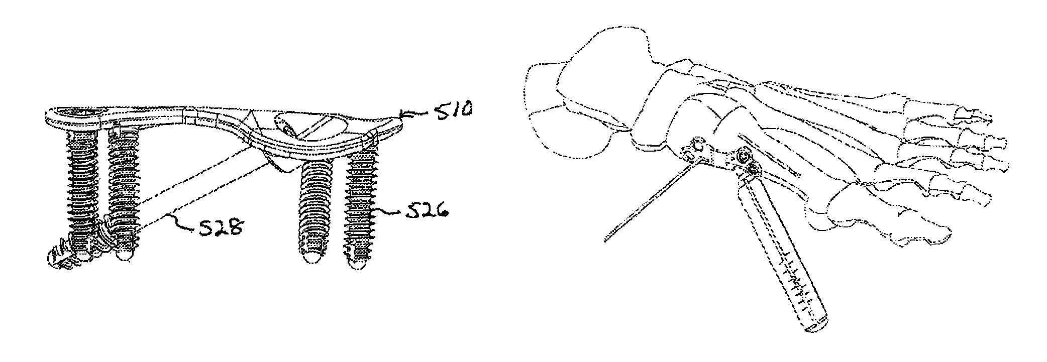
[0054]FIGS. 18-28 illustrate the invention which is a lapidus plate and assembly designed for use in lapidus procedures. This plate 510 has a first end 512 and a second end 518, where the first end includes two tabs 515, each having internally threaded locking screw holes 514. A second end 518 has three conjoined tabs or lobes 515 two of which include internally threaded locking screw holes 514. The third lobe includes a compression housing 516 that projects into the plate so as to provide a seat for a compression screw and a structure that will also contribute to this compression in the bone. Once again, this compression housing is a peripheral compression housing that is not located on the spine or longitudinal axis of the plate, and the screw located in this housing does not act to apply a force substantially solely in the direction of the longitudinal axis or along the spine of the plate, but rather acts so as to apply a compound force that is directed in a diagonal direction ac...


PUM


Abstract

An orthopedic plate has a first end including a locking screw hole that receives a locking screw and spaced from that hole is a closed compression housing that extends from the bone-facing side of the plate and which receives a compression screw that forms an angle of from about 10° to about 70° with a longitudinal axis of the plate. The compression housing is not located on the medial line of the plate, but is peripheral to the medial line, either in the longitudinal or the medial direction of the plate.

Description

CROSS REFERENCE[0001]This Application claims the benefit of priority under 35 U.S.C. §119 of U.S. Provisional Application Ser. No. 61 / 580,680, filed on Dec. 28, 2011, and as a Continuation-in-Part Application of U.S. patent Ser. No. 13 / 372,902 filed Feb. 14, 2012, herein fully incorporated by reference.FIELD OF THE INVENTION[0002]The present invention relates to an orthopedic plate, which is configured to increase compression at a bone interface, in particular to stabilize bones or bone fragments relative to each other such as to cause fusion. Specific embodiments and methods of fixation are presented for fixation of the bones of the foot including, for example, stabilization of a fracture, dislocation or reconstruction of a deformity such as use in osteotomies and bunionectomies. The invention also applies to fusion procedures in other areas of the body, including the wrist or hand. The plate has a compression structure located generally peripherally to the mass of the plate, which...

Claims


Application Information

Patent Timeline
Patent Type & Authority Patents(United States)
IPC IPC(8): A61B17/66A61B17/80
CPCA61B17/8061A61B17/8014A61B17/8095A61B17/8057A61B17/8605
Inventor LEWIS, DEREK S.ALTENAU, ELIZABETHBENNETT, GORDONDEN HARTOG, BRYAN D.HEAVENER, JACKSON R.HOCKETT, BRIANJOHNSON, JEFFREYKAY, DAVID B.LEITHER, ANDREWPOKORNEY, ELLENWRIGHT, ALLISON
Owner ORTHOHELIX SURGICAL DESIGNS
Why Eureka
Try Eureka