Flex tactical cable splice

a technology of fiber optic cables and protectors, applied in the direction of optics, fibre mechanical structures, instruments, etc., can solve the problems of unable to wind the repaired cable onto the spool, the individual fibers within the fiber optic cable containing multiple individual optical fibers to be broken or damaged, and the difficulty of pulling or pulling the cable to the desired location

Inactive Publication Date: 2015-06-23
ADVANCED FIBER PROD LTD
View PDF9 Cites 15 Cited by
  • Summary
  • Abstract
  • Description
  • Claims
  • Application Information

AI Technical Summary

Problems solved by technology

In such harsh environments, it is not uncommon for individual fibers within a fiber optic cable containing multiple individual optical fibers to be broken or damaged.
When such a break occurs, it is typically necessary to repair the broken fiber or fibers at location of the malfunction.
Furthermore, if a repaired section of an optical cable is not flexible or has a significantly larger diameter than the remaining undamaged portion of the cable, it becomes difficult to wind such repaired cable onto the spool.
Additionally, if a portion of the repaired cable has a larger diameter than the undamaged sections, it becomes difficult to pull or drag the cable to a desired location because the repaired section or portion having a larger diameter can get caught on corners and edges when the cable is being threaded or dragged for deployment.
Conventional techniques and methods for repairing broken fibers within an optical cable generally result in the repaired section being substantially more rigid than the undamaged sections of the cable.
Moreover, such conventional techniques typically result in the repaired section being substantially larger in diameter than the undamaged sections of the cable.

Method used


Image

  • Flex tactical cable splice
  • Flex tactical cable splice
  • Flex tactical cable splice

Examples


Embodiment Construction

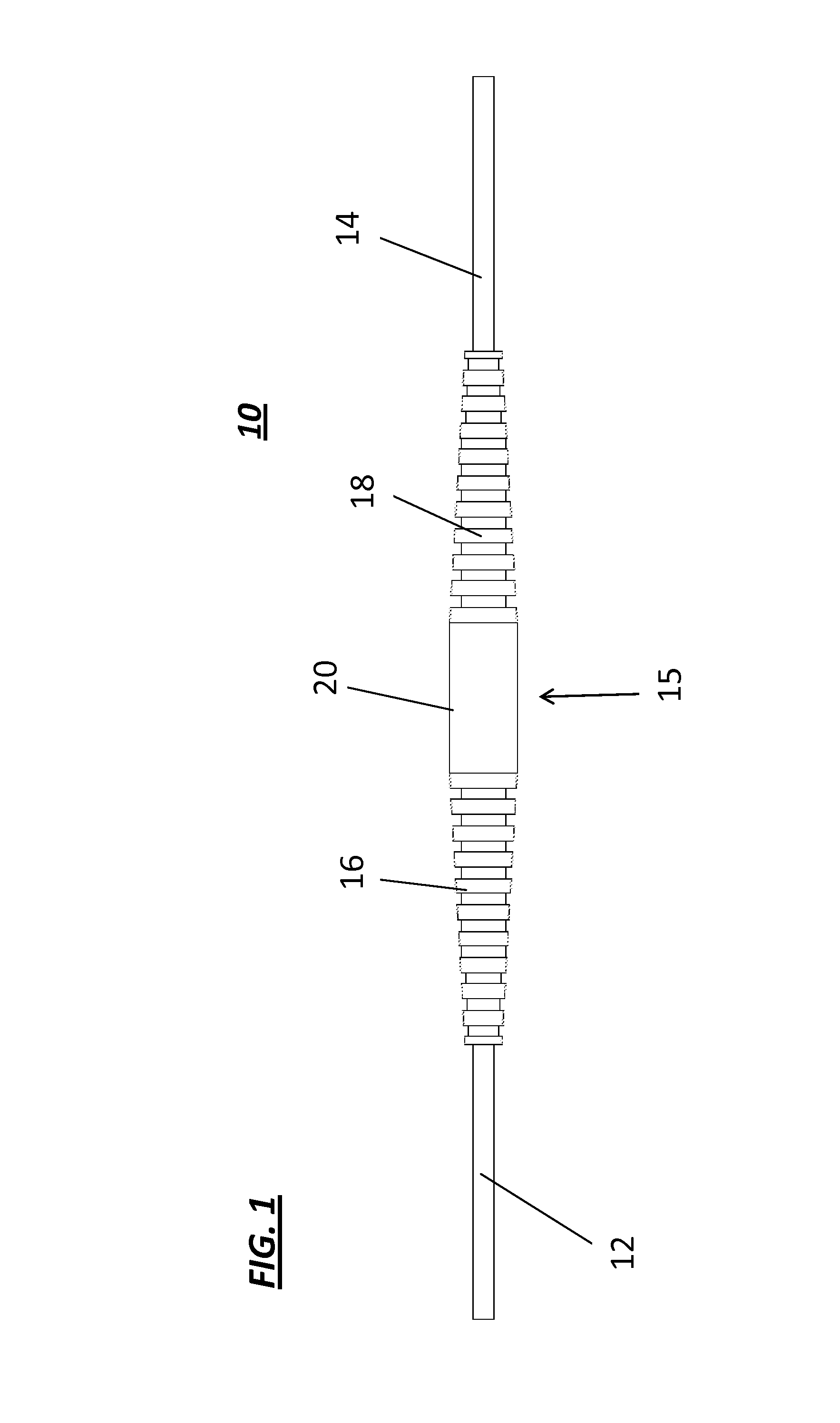
[0023]Referring now to the drawings, FIG. 1 illustrates an optical fiber or fiber optic splice protector 10 configured in accordance with the present invention. The splice protector 10 securely connects opposing ends 12 and 14 of an optical cable containing at least one optical fiber therein that has been repaired by splicing, preferably using fusion splicing techniques. Also illustrated in accordance with the present invention are first and second flexible sleeves 16, 18 which are coupled together at the location of the spliced fiber or fibers. A low-temp glue or other over molding and re-protection material 20 is applied to coupling 15 to enclose, surround and environmentally seal the spliced optical fiber or fibers contained inside. The flexible sleeves 16,18 are preferably constructed of a flexible material such at rubber or a flexible plastic.

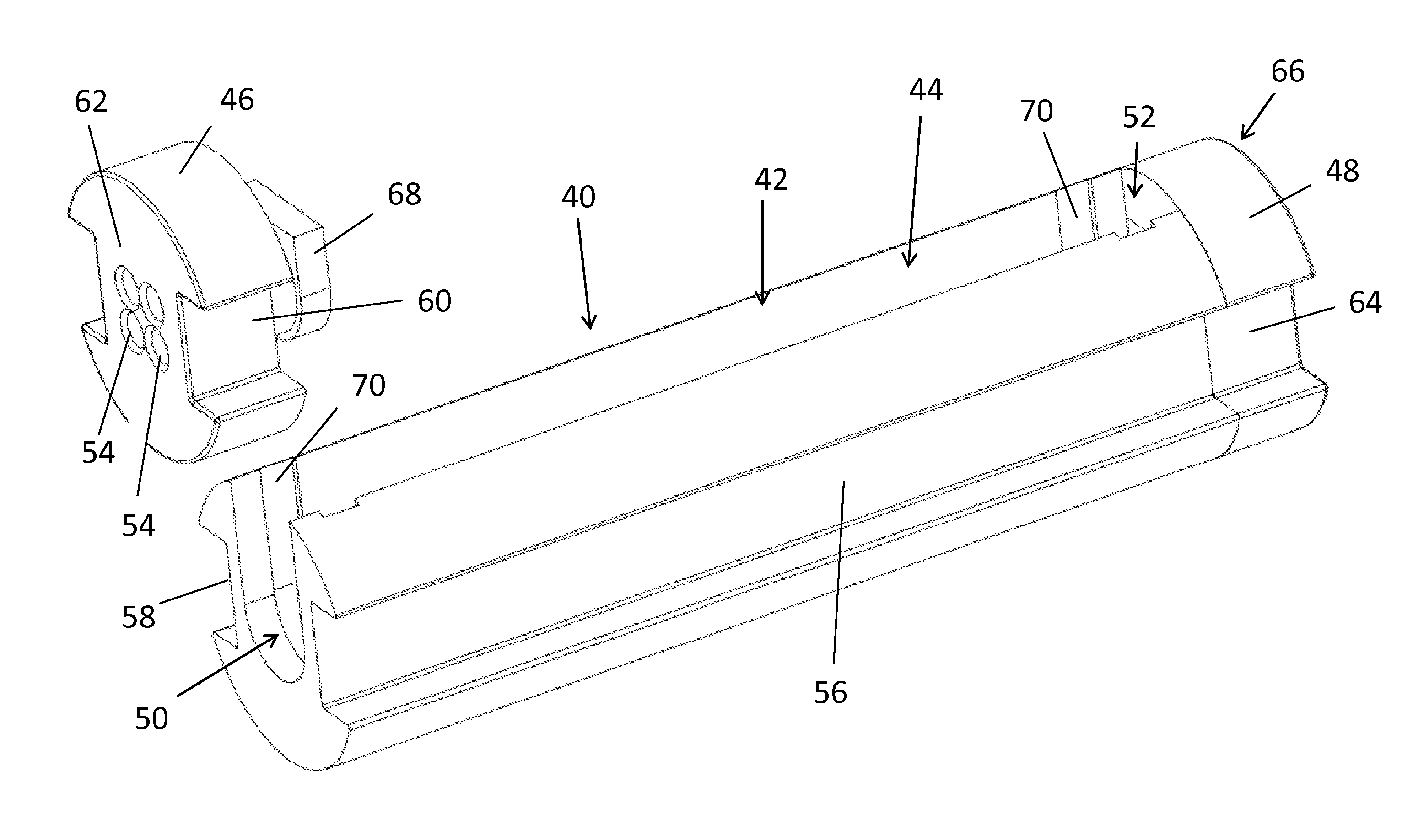
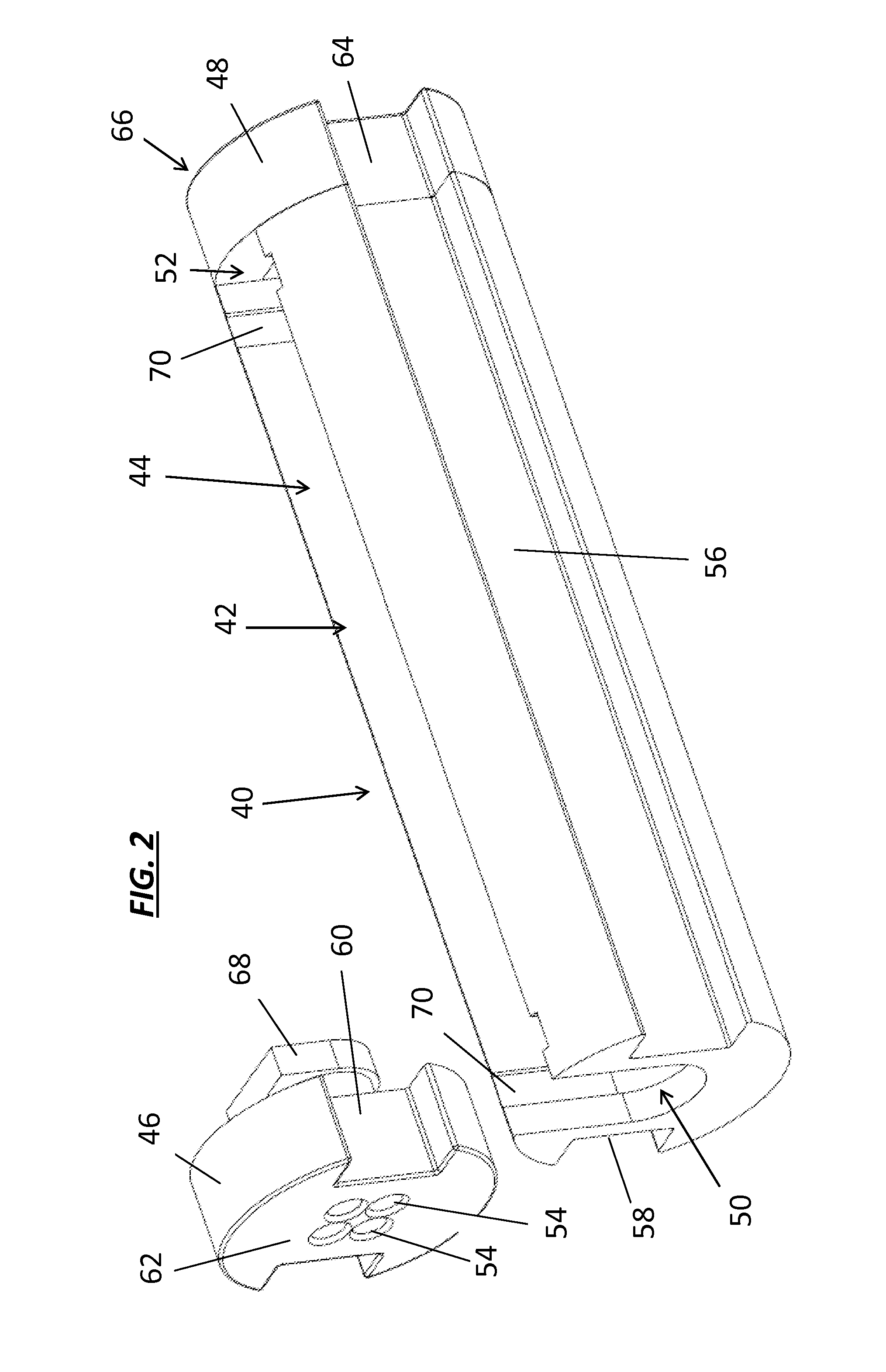
[0024]FIG. 2 illustrates a body 40 of a splice protector configured to form a trough having an opening 42 to a chamber 44 contained there...


PUM

PropertyMeasurementUnit
insertion lossaaaaaaaaaa
flexibleaaaaaaaaaa

Abstract

A splice protector is provided having a trough configuration body form a chamber therein with first and second openings at opposing ends of the body, and first and second end caps coupled to the first and second openings of the body of the splice protector, the first and second separable end caps each including at least one channel for passing through an optical fiber. At least one optical core having been coupled using fusion splicing, passes through the channels of the first and second end caps and the chamber, wherein the splice is located within the chamber, and a flexible filler is filled within the chamber to secure the spliced fibers therein.

Description

BACKGROUND OF THE INVENTION[0001]1. Field of the Invention[0002]The present invention relates generally to splicing protectors for fiber optic cables, and more particularly, to a military grade and outside broadcast grade fiber optic cable splice protector with improved flexibility and reduced length and size.[0003]2. Description of Related Art[0004]Fiber optic cables have a plurality of uses, including being utilized in rugged and harsh environments such as tactical military and outside broadcast uses. In such harsh environments, it is not uncommon for individual fibers within a fiber optic cable containing multiple individual optical fibers to be broken or damaged. When such a break occurs, it is typically necessary to repair the broken fiber or fibers at location of the malfunction.[0005]Two optical fiber splicing methods are commonly used for permanently joining together a broken optical fiber. Both splicing methods provide much lower insertion loss compared to fiber optic conne...

Claims


Application Information

Patent Timeline
Patent Type & Authority Patents(United States)
IPC IPC(8): G02B6/255G02B6/44
CPCG02B6/2558Y10T29/49739G02B6/4477
Inventor DURRANT, RICHARD COLIN EDWARDHELMICK, ROGER KEVIN
Owner ADVANCED FIBER PROD LTD
Why Eureka
Try Eureka