Method of fusion splicing thermally dissimilar glass fibers

a technology of thermally dissimilar glass fibers and fusion splicing, which is applied in the direction of optical elements, manufacturing tools, instruments, etc., can solve the problems of ineffective thermal diffusion between the two fibers, damage to the high-temperature fiber, rough cut or twisted surface, etc., to reduce the direct heating of the low-temperature fiber, improve thermal diffusion, and maximize the temperature gradient

Inactive Publication Date: 2005-07-26
NP PHOTONICS A CORP OF DELAWARE
View PDF12 Cites 15 Cited by
  • Summary
  • Abstract
  • Description
  • Claims
  • Application Information

AI Technical Summary

Benefits of technology

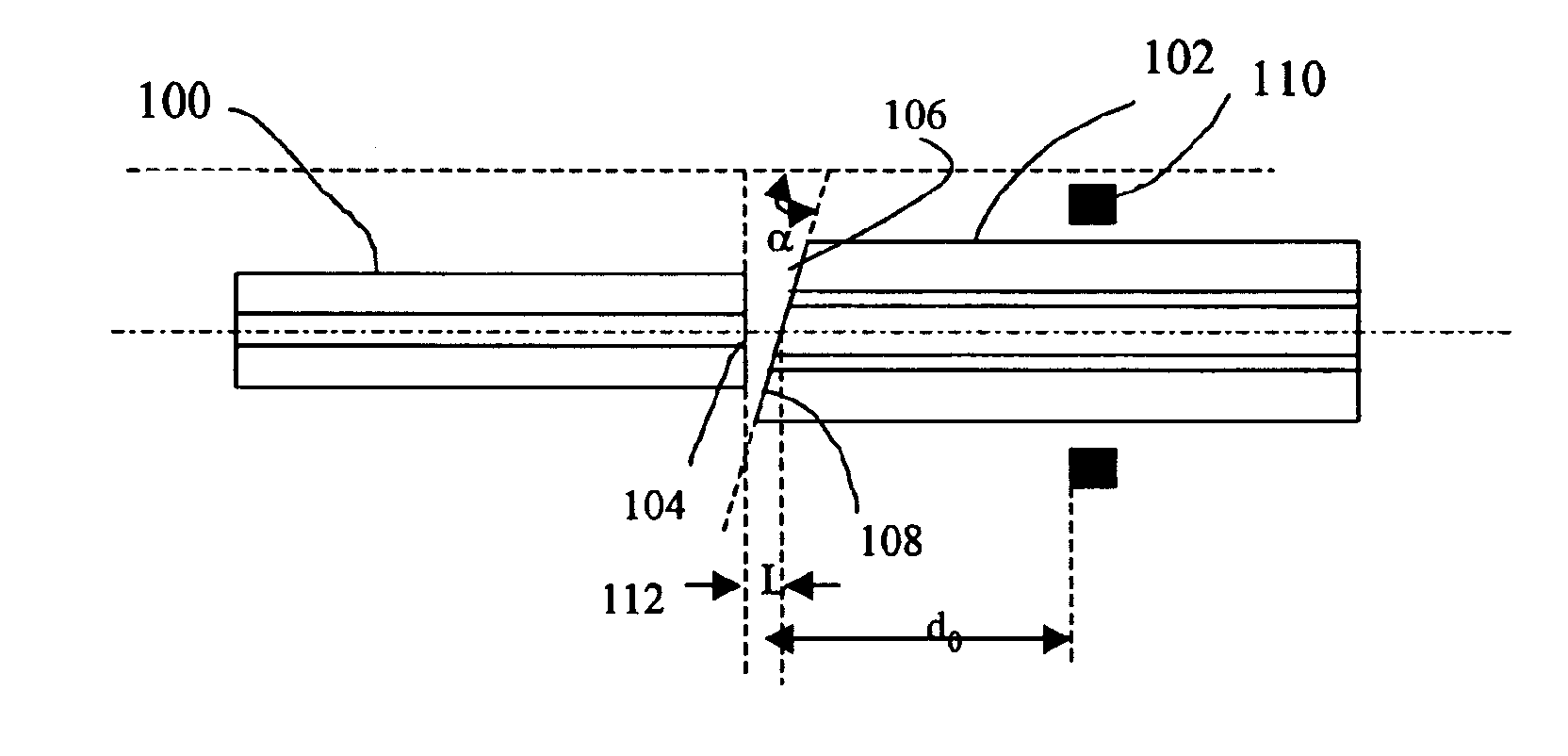
[0011]In another embodiment, the fibers are asymmetrically heated so that the temperature at the end of the high-temperature fiber is greater than the temperature at the end of the low-temperature fiber. This temperature gradient serves to improve thermal diffusion between the two fibers when brought into contact thereby strengthening the fusion splice. Asymmetric heating is achieved by placing the heating element along the high-temperature fiber at a distance do from the splice so that the temperature is highest at a point on the high-temperature fiber away from the fiber tip. The heat is preferably localized onto the high-temperature fiber, which reduces the direct heating of the low-temperature fiber, to maximize the temperature gradient and increase bond strength.
[0012]In another embodiment, the high-temperature fiber is angle cleaved and the low-temperature fiber is square cleaved. The end of the low-temperature fiber forms a matched angle in situ during the splicing process. This method avoids angle cleaving of the low-temperature fiber and the alignment of two angle-cleaved fibers, which are low yield and time consuming processes. In another embodiment, the tip of the angle-cleaved fiber is polished flat back to the core to reduce the range of motion of the low-temperature fiber during splicing. In yet another embodiment, the low-temperature fiber is provided with an outer cladding layer that is chemically and thermally compatible with both the low and high temperature glasses.

Problems solved by technology

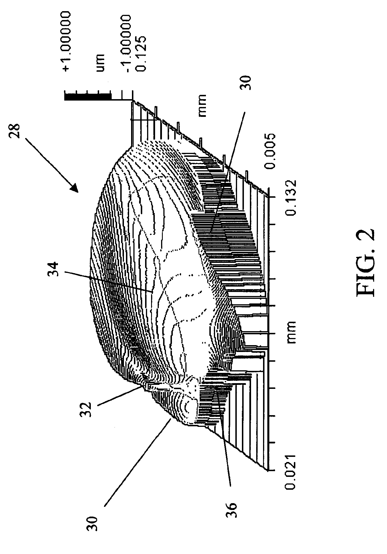
However, cleaving damages the high-temperature fiber and leaves a rough cut or twisted surface.
The problem is particularly acute in double-clad fiber at the interface between the cladding layers.
Because the high-temperature fiber is not softened, these imperfections remain and produce or exacerbate macro and / or micro cracks at the fusion joint due to imperfect contact, hence ineffective thermal diffusion between the two fibers.

Method used


Image

  • Method of fusion splicing thermally dissimilar glass fibers
  • Method of fusion splicing thermally dissimilar glass fibers
  • Method of fusion splicing thermally dissimilar glass fibers

Examples


Embodiment Construction

[0029]The present invention provides a mechanically robust fusion splice between a high-temperature fiber and a specialty low-temperature glass fiber. This type of fusion splice is particularly useful in and was motivated by the development of compact optical components such as fiber amplifiers and lasers. To eliminate fiber management and reduce package size one must use a glass fiber that provides high gain per unit length. This in turn dictates a glass such as a multi-component glass (phosphorus oxide P2O5, germanium oxide GeO2 or telluride oxide TeO2) that has a high solubility of rare-earth dopants such as erbium and ytterbium and exhibits the necessary spectroscopic properties. These glasses have a much lower softening point temperature than standard silica glass.

[0030]To avoid seriously degrading if not destroying the multi-component glass fiber when spliced to the silica fiber, it was determined through extensive testing that a lower splice temperature sufficient to soften b...


PUM

PropertyMeasurementUnit
softening temperaturesaaaaaaaaaa

Abstract

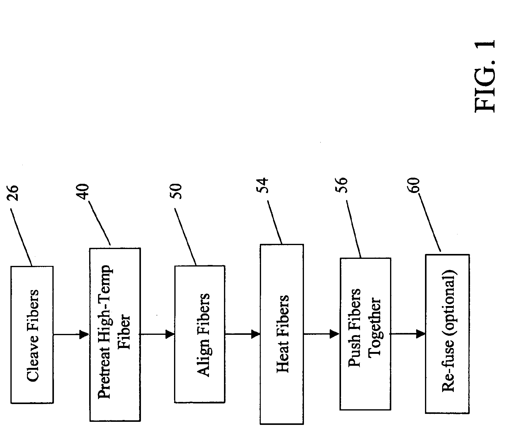
Thermally dissimilar glass fibers are fusion spliced by pretreating the cleaved end surface of the high-temperature fiber to provide a smooth surface for making good contact with the low-temperature fiber. The fibers are heated to a temperature that is high enough to soften the low-temperature fiber but not the high-temperature fiber and brought in contact to form the fusion joint.

Description

CROSS-REFERENCE TO RELATED APPLICATIONS[0001]This application is a continuation-in-part of application Ser. No. 09 / 963,727 entitled “Method of Fusion Splicing Silica Fiber with Low-Temperature Multi-Component Glass Fiber” filed on Sep. 26, 2001, now U.S. Pat. No. 6,705,771 and is a continuation-in-part of Ser. No. 10 / 374,001 entitled “Method of Angle Fusion Splicing Silica Fiber with Low-Temperature Non-Silica Fiber” filed on Feb. 25, 2003 the entire contents of which are incorporated by reference.BACKGROUND OF THE INVENTION[0002]1. Field of the Invention[0003]The present invention relates to the field of fusion splicing optical fibers, and more specifically, to the fusion splicing of thermally dissimilar glass fibers, that is glass fibers with substantially different softening temperatures.[0004]2. Description of the Related Art[0005]In the field of fiber optics, fiber splicing is a well-known and widely practiced technique. Typically, the fibers are brought close to each other and...

Claims


Application Information

Patent Timeline
Patent Type & Authority Patents(United States)
IPC IPC(8): G02B6/255
CPCG02B6/2551G02B6/2552G02B6/03638
Inventor LI, WEIJIONGCHAVEZ-PIRSON, ARTUROMERZLYAK, EUGENEPAYSNOE, GARYSTEWARD, BRYANTIAN, WENYANJIANG, SHIBIN
Owner NP PHOTONICS A CORP OF DELAWARE
Why Eureka
Try Eureka