Heat dissipation assembly incorporated into a handguard surrounding a rifle barrel

a technology for handguards and rifle barrels, applied in the direction of barrel mounting, butts, weapons, etc., can solve the problem of rapid heating of barrels, and achieve the effect of preventing overheating of barrels

Inactive Publication Date: 2017-12-12
BYBEE ERIN
View PDF30 Cites 18 Cited by
  • Summary
  • Abstract
  • Description
  • Claims
  • Application Information

AI Technical Summary

Benefits of technology

[0010]In a second variant, a fan is substituted for the piezo-electric blower and the circular blade substituted by a vortex effect created by intake flow patterns created by the fan which facilitates wicking away of heat from the barrel, via the handguard incorporated hot plate to exteriorly supported cooling plates. An air tube is attached directly to an interior of the handguard, in abutting contact with the barrel nut. The air tube exhibits a plurality of slot configured on its abutting end face which causes the airflow to be rotated and compressed in a torsionally directed fashion around the barrel separate from the heat transfer from the barrel nut to the hot plate.
[0011]In operation, the assembly converts the emanating heat from the barrel to either of the piezo-blower operated rotary fan or air blade, which operates to both discharge heat emanating from the barrel as well as to draw, via forced convention in the one variant or torsionally generated airflow in the other variant, a cooling airflow to assist in preventing overheating of the barrel. Air intake vents formed in the hand guard overlap the fins for assisting in convection resulting from pulling of the cooling air over the fins.

Problems solved by technology

As is known, repeated discharge of rounds in either of semi-automatic or automatic firing modes results in rapid heating of the barrel to an excessive degree, resulting in the requirement to provide for cooling of the barrel to prevent damage or a misfiring condition.

Method used


Image

  • Heat dissipation assembly incorporated into a handguard surrounding a rifle barrel
  • Heat dissipation assembly incorporated into a handguard surrounding a rifle barrel
  • Heat dissipation assembly incorporated into a handguard surrounding a rifle barrel

Examples


Embodiment Construction

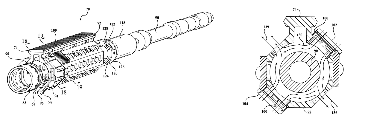
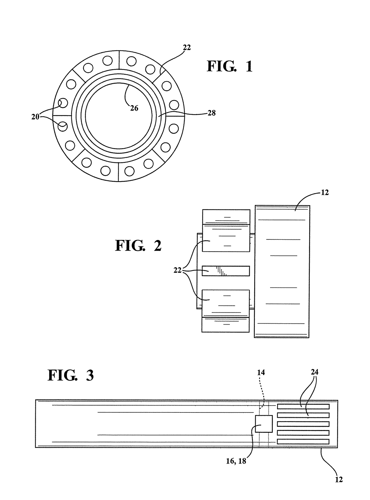
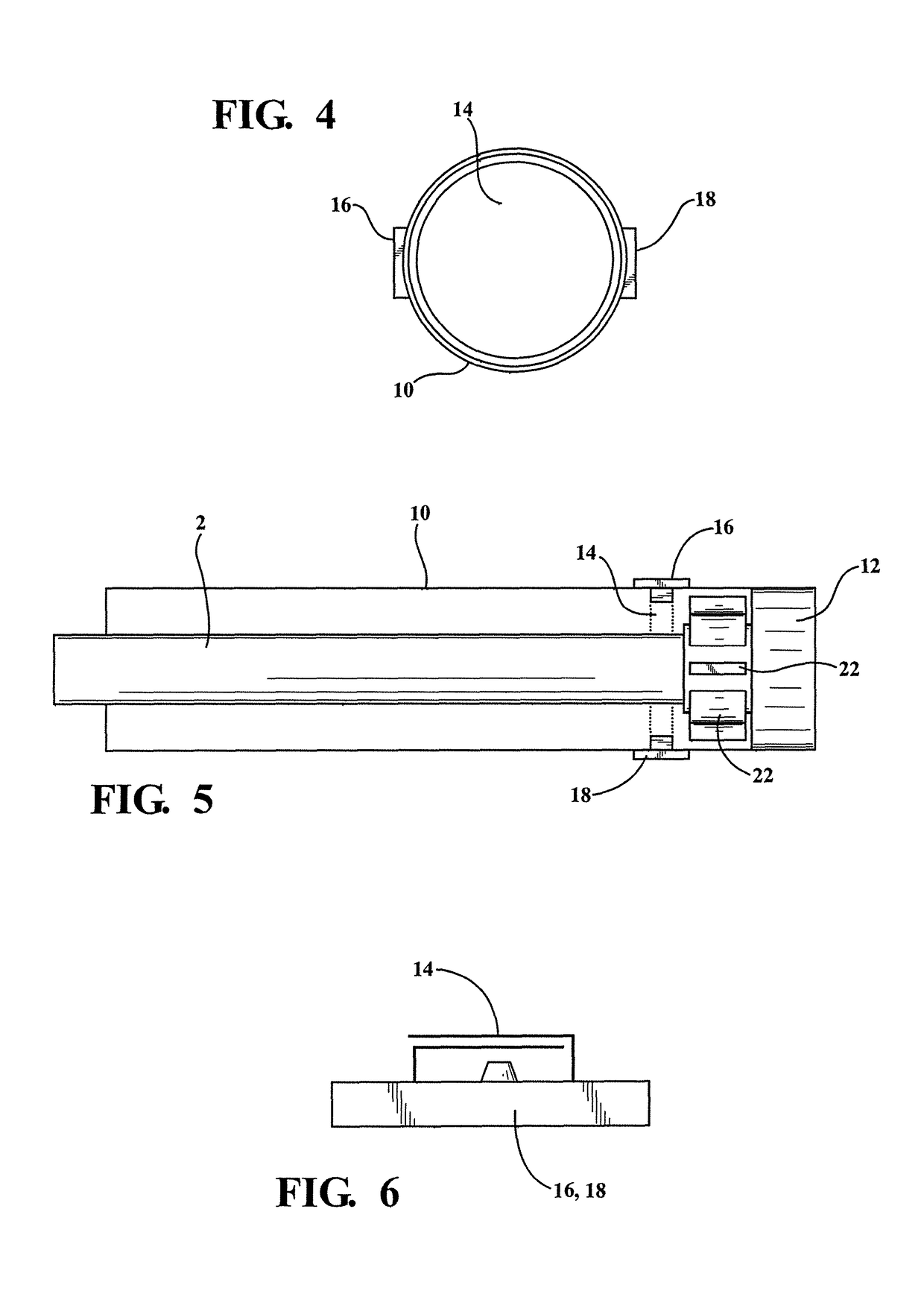
[0032]As previously described, the present invention discloses a rifle hand guard assembly incorporating heat dissipating structure, such as in the form of a thermo-electric generator utilizing a Seebeck module arranged between a heat sink and cooling block and which absorbs heat emanating from the rifle barrel. As will be further described with reference to the appended illustrations, the module powers a piezoelectric blower which in turn integrates an inner diaphragm, piezoelectric element and pump in order to create an airflow through a nozzle for in turn driving a circular air blade integrated into an elongated tube mounted over the rifle barrel.

[0033]The tube (also termed a free floating handguard) is mounted in thermally conducting fashion with the rifle barrel and is in contact with cooling fins arranged on an end assembled cooling block, the fins being arrayed in circumferential and linearly extending fashion around an attached barrel nut for converting the emanating heat fr...


PUM


Abstract

A heat dissipation assembly for use with a barrel forming a part of a firearm upper receiver. An annular shaped barrel nut is adapted to secure the barrel to the upper receiver. An elongated handguard is affixed to the barrel nut at a heat conducting location, the handguard adapted to surround a proximal extending portion of the barrel, the handguard having a plurality of apertures defined therethrough. At least one cooling element is located on an exterior of the handguard. A thermoelectric generator is incorporated into the handguard for transferring heat from the barrel nut to the cooling element. A fan component is integrated into the handguard and operated by the thermoelectric generator for drawing air through the apertures in order to provide additional cooling to the barrel.

Description

CROSS-REFERENCE TO RELATED APPLICATIONS[0001]This Application claims the benefit of U.S. Provisional Application 62 / 171,303 filed on Jun. 5, 2015, the contents of which is incorporated herein in its entirety,FIELD OF THE INVENTION[0002]A rifle hand guard assembly incorporating heat dissipating structure in the form of a thermo-electric generator utilizing a Seebeck module arranged between a heat sink and cooling block and which absorbs heat emanating from the rifle barrel. In a first variant, the module powers a piezoelectric blower which in turn integrates an inner diaphragm, piezoelectric element and pump in order to create an airflow through a nozzle for in turn driving a circular air blade integrated into an elongated tube mounted over the rifle barrel.[0003]In a second variant, a fan is substituted for the piezo-electric blower and the circular blade substituted by a vortex effect created by intake flow patterns created by the fan which facilitates wicking away of heat from the...

Claims


Application Information

Patent Timeline
Patent Type & Authority Patents(United States)
IPC IPC(8): F41A13/12F41C23/16F41A21/24F41A13/10F41A21/48
CPCF41A13/10F41C23/16F41A21/24F41A21/48
Inventor BYBEE, BRADLEY W.
Owner BYBEE ERIN
Why Eureka
Try Eureka