Optical fiber welding machine and welding method

An optical fiber and butt joint technology, which is applied in the field of optical fiber fusion splicing machine and fusion splicing connection, can solve the problems of complicated operation and inability to be simple.

Inactive Publication Date: 2003-02-26
THE FUJIKURA CABLE WORKS LTD
View PDF2 Cites 19 Cited by
  • Summary
  • Abstract
  • Description
  • Claims
  • Application Information

AI Technical Summary

Problems solved by technology

[0007] In addition, in JP-A-2000-275469, the mode field diameter is estimated for the optical fiber after initial heating (heating for fusion splicing) and additional heating only by image observation. On the optical

Method used


Image

  • Optical fiber welding machine and welding method
  • Optical fiber welding machine and welding method
  • Optical fiber welding machine and welding method

Examples


Embodiment Construction

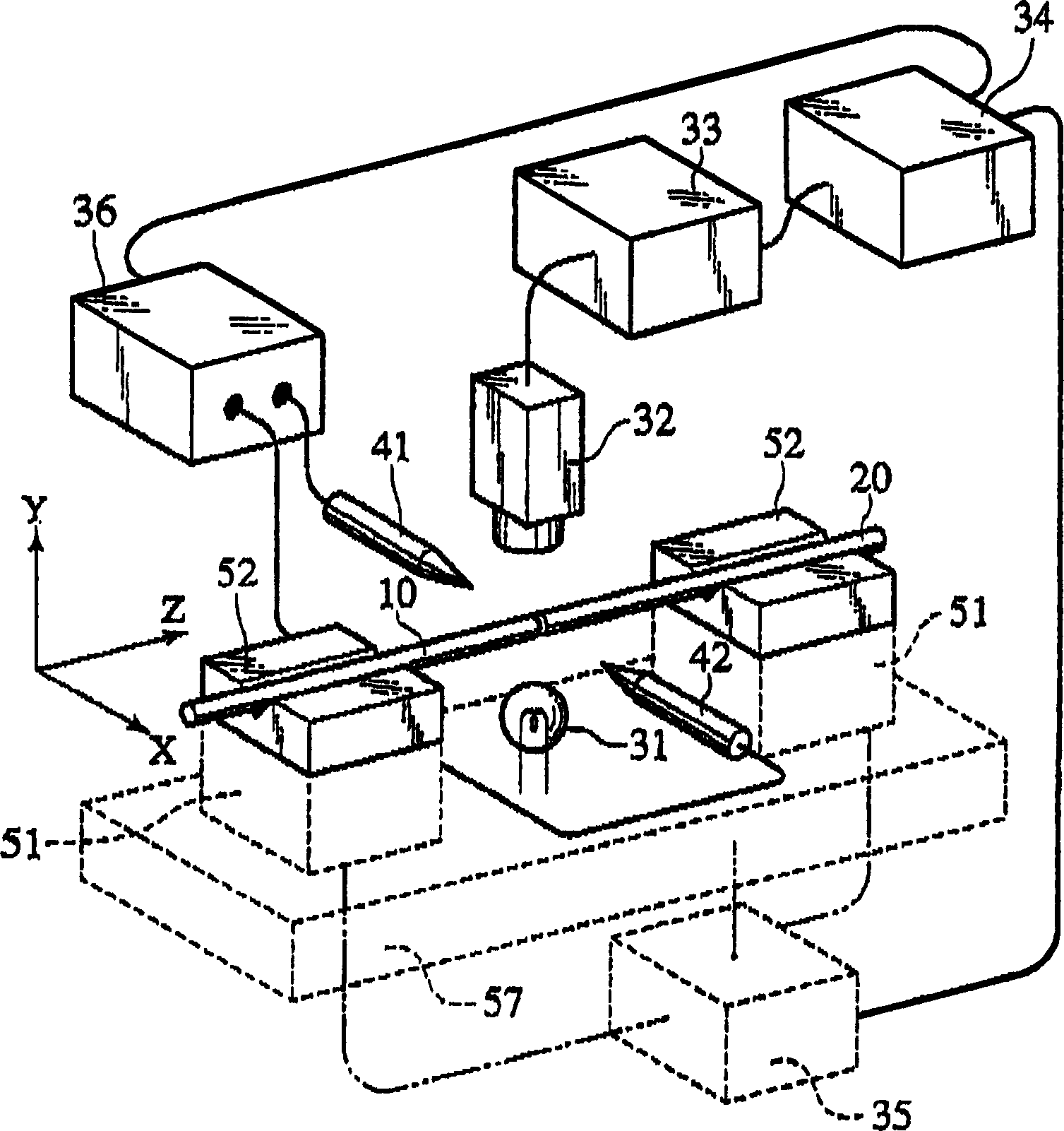
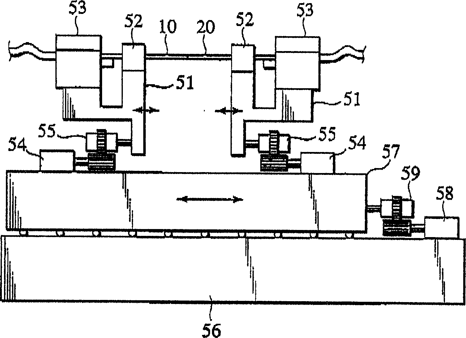
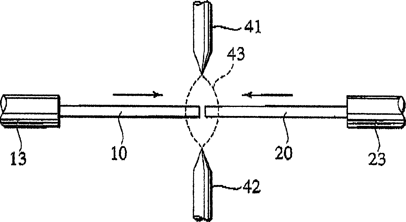
[0036] Hereinafter, embodiments of the present invention will be described in detail with reference to the drawings. figure 1 It is a schematic diagram conceptually showing an optical fiber fusion splicing machine according to an embodiment of the present invention. in the figure 1 Among them, the V-groove bases 52, 52 are used to respectively set the two optical fibers 10, 20 to be connected and place them on the moving bases 51, 51. These moving bases 51, 51 can move along the directions of X, Y, and Z axes. Here, the axial direction (horizontal direction) of the optical fibers 10, 20 is defined as the Z-axis, the horizontal direction at right angles to the axes of the optical fibers 10, 20 is defined as the X-axis, and the vertical direction at right angles to the axes of the optical fibers 10, 20 is defined as the X-axis. The direction is taken as the Y axis. These moving seats 51, 51 are placed on the movable base 57, and the movable base 57 moves along the Z axis, so ...


PUM


Abstract

A fusion splicer and fusion splicing method for optical fibers is disclosed including a TV camera 32 which obtains transmitted light images passing through side areas of respective optical fibers 10, 20, an image processing unit 33 which calculates mode field diameters of the respective optical fibers from brightness distributions of the images in terms of directions traverse to the optical fibers to calculate a diametric difference between the mode field diameters, a movable base 57 to move abutted portions between the optical fibers relative to an electric discharge beam position, a drive unit 35 which implements additional electric discharge heating after applying electric discharge fusion splicing heating to the abutted portions while moving the electric discharge beam position toward one of the optical fibers, of which mode field diameter is regarded to be small, and a control unit 34 which controls an electric discharge power supply 36.

Description

technical field [0001] The present invention relates to an optical fiber fusion splicing machine and an optical fiber fusion splicing method for splicing and splicing two optical fibers having different mode field diameters by arc discharge. Background technique [0002] When constructing a communication optical cable network and manufacturing a device using an optical fiber, it often happens that two optical fibers having different mode field diameters are fused and connected to each other. At this time, when these two optical fibers are fusion-coupled to each other using only an arc discharge fusion splicing machine, the connection loss is larger than when optical fibers having the same mode field diameter are connected to each other. [0003] Therefore, attempts have been made to connect two optical fibers having different mode field diameters to each other with as low a loss as possible. For example, in JP-A-2000-098171, it is proposed that when the optical fiber on the...

Claims


Application Information

Patent Timeline
IPC IPC(8): G02B6/255
CPCG02B6/2551G02B6/255
Inventor 齐藤茂川西纪行窪敏喜
Owner THE FUJIKURA CABLE WORKS LTD
Why Eureka
Try Eureka