
Optical fiber fusion splicer

Active Publication Date: 2014-03-27
THE FUJIKURA CABLE WORKS LTD
View PDF3 Cites 15 Cited by
  • Summary
  • Abstract
  • Description
  • Claims
  • Application Information

AI Technical Summary

Benefits of technology

The invention provides a coating clamp for optical fiber fusion splicers that has a feature that makes it easier to open without damaging the components. The clamp has an elastic member that helps the lid to open and a design that prevents the lid from hitting the driving force transmission system. This makes it possible to manually open the lid without causing any harm to the machinery.

Problems solved by technology

For this reason, there is a case where the operation of opening the coating clamp and taking out an optical fiber after the completion of a proof test takes substantial time and effort.
Accordingly, similar to the Coating clamp system fusion splicer, even regarding the Fiber holder system fusion splicer, there is a case where the operation of opening the coating clamp and taking out an optical fiber after the completion of a proof test takes substantial time and effort.
For this reason, when the lid plate opening and closing motor is assembled into the fusion splicer, apparatus designs are greatly influenced, and an increase in size and cost of the fusion splicer is unavoidable.
Additionally, since the motor driven coating clamp grips an optical fiber between the base plate and the lid plate with the driving force of the motor, it is necessary to continue supplying electric power to the motor in order to maintain gripping and fixing of a covered portion of the optical fiber, and the amount of power consumed is large.

Method used


Image

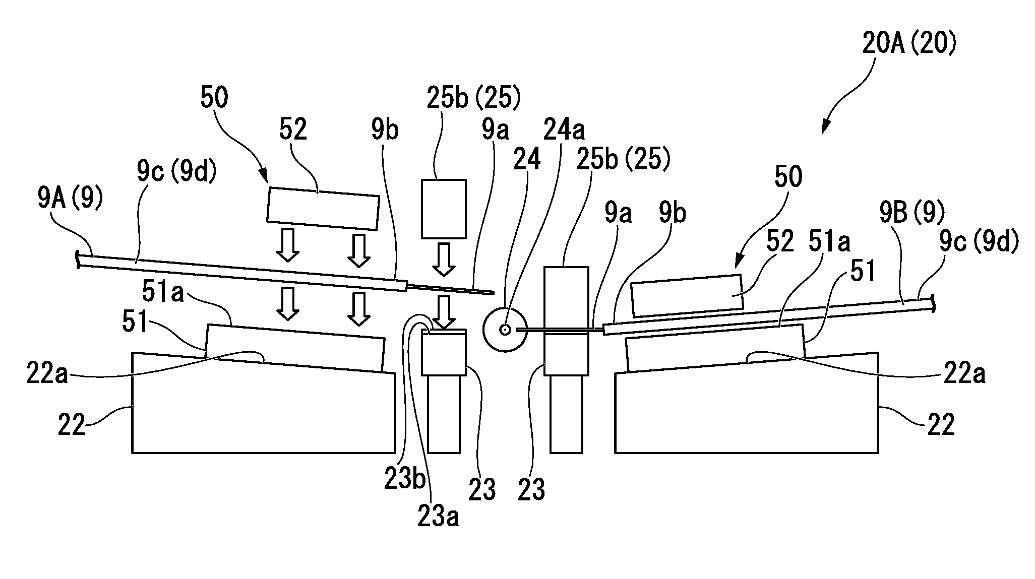
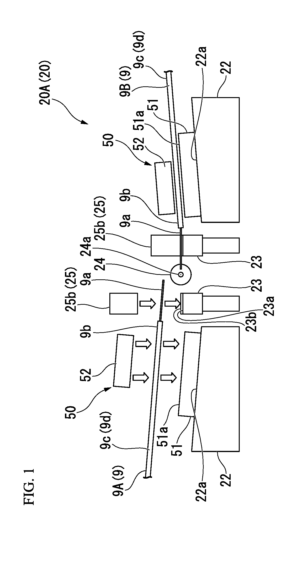
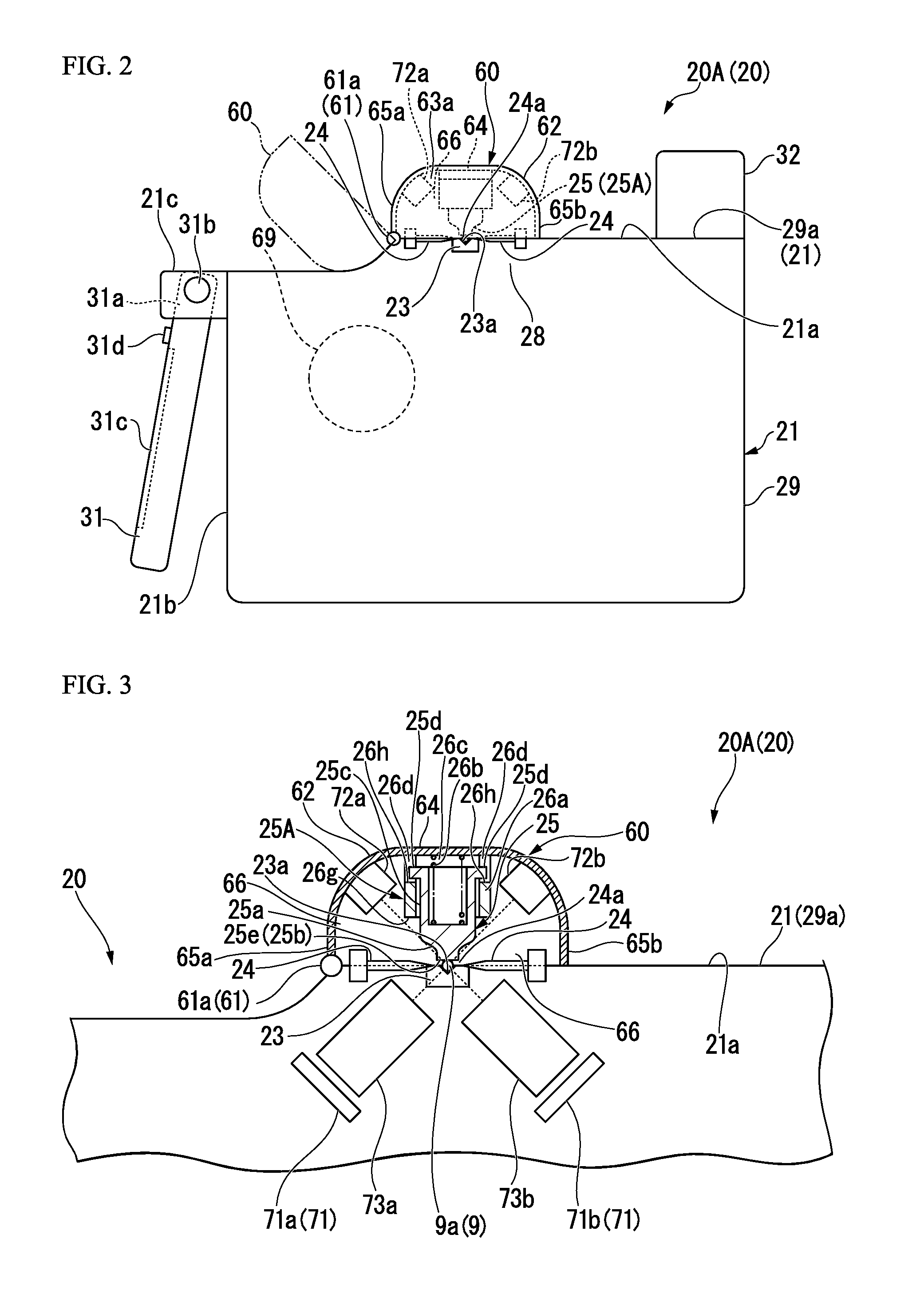
  • Optical fiber fusion splicer
  • Optical fiber fusion splicer
  • Optical fiber fusion splicer

Examples


modification example

[0769](Modification Example of Coating Clamp Installation Base)

[0770]FIG. 23 shows a modification example of the movable stage (coating clamp installation base).

[0771]In the movable stage 22A (coating clamp installation base) shown in FIG. 23, the movable stage 22 illustrated in FIGS. 6A to 1413 and the like is provided with a pin supporting protrusion 22f used to support the thrust-up pin 54.

[0772]Additionally, FIG. 23 shows an installation base 22P with a thrust-up pin with a configuration in which the thrust-up pin 54 is elevatably provided at the movable stage 22A.

[0773]In addition, in the present specification, the installation base 22P with a thrust-up pin is also treated as functioning as the coating clamp installation base.

[0774]As shown in FIG. 23, the movable stage 22A is provided so that the pin supporting protrusion 22f protrudes to the side surface of the installation base body 22a of the movable stage 22 illustrated in FIGS. 6A to 14B and the like, on one side in the s...


PUM

PropertyMeasurementUnit
Forceaaaaaaaaaa
Poweraaaaaaaaaa
Magnetismaaaaaaaaaa

Abstract

An optical fiber fusion splicer that heats and fusion-splices optical fibers to each other, the optical fiber fusion splicer includes: a coating clamp installation base; a coating clamp that is attached to the coating clamp installation base and has a coating clamp lid that is openable and closable; and a first power source for advancing the coating clamp installation base and opening the coating clamp lid. An operation of opening the coating clamp lid is performed using the first power source after the fusion splicing is completed.

Description

CROSS REFERENCE TO RELATED APPLICATIONS[0001]This application is a continuation application based on a PCT Patent Application No. PCT / JP2013 / 056109, filed Mar. 6, 2013, whose priority is claimed on Japanese Patent Application No. 2012-78259, filed Mar. 29, 2012, Japanese Patent Application No. 2012-206309, filed Sep. 19, 2012, and Japanese Patent Application No. 2012-272849, filed Dec. 13, 2012, the entire content of which are hereby incorporated by reference.BACKGROUND OF THE INVENTION[0002]1. Field of the Invention[0003]The present invention relates to an optical fiber fusion splicer, and particularly, to an optical fiber fusion splicer that has coating clamp installation bases, which advance and retract with respect to a heating and fusing portion that heats and fusion-splices optical fibers to each other, on both sides of the heating and fusing portion and that is provided with coating clamps for gripping and fixing the optical fibers on the coating clamp installation bases.[000...

Claims


Application Information

Patent Timeline
IPC IPC(8): G02B6/255
CPCG02B6/2553G02B6/24G02B6/255
Inventor IWASHITA, YOSHINORI
Owner THE FUJIKURA CABLE WORKS LTD
Learn More