Reinforcing member for optical fiber fusion-splicing portion and reinforcing method therefor

a technology of reinforcing member and optical fiber, which is applied in the field of reinforcing member, can solve the problems of large size of junction boxes, and achieve the effect of low cost and efficient assembly

Inactive Publication Date: 2012-09-27
SUMITOMO ELECTRIC IND LTD
View PDF2 Cites 19 Cited by
  • Summary
  • Abstract
  • Description
  • Claims
  • Application Information

AI Technical Summary

Benefits of technology

[0012]According to an embodiment of the invention, all the tube-shaped heat-fusible adhesive members, without the tensile strength body between, in one of the space portions formed between the tensile strength body and the heat-shrinkable tube, are arranged in array or in a trefoil formation state. Therefore, as a heater for heat-processing, a heater having a heating surface of not the special shape but the simply planar shape can be used, which can create low cost. Further, the coated optical fibers, without coming into contact with one another by the individual tube-shaped heat-fusible adhesive members, can be efficiently assembled together, being clamped by a clamp part having no especially large size.

Problems solved by technology

At this time, in case that the fusion-splicing optical fibers are reinforced one by one, large space is required in order to accommodate reinforcing members, so that there is a problem that the junction box becomes large in size.

Method used


Image

  • Reinforcing member for optical fiber fusion-splicing portion and reinforcing method therefor
  • Reinforcing member for optical fiber fusion-splicing portion and reinforcing method therefor
  • Reinforcing member for optical fiber fusion-splicing portion and reinforcing method therefor

Examples


Embodiment Construction

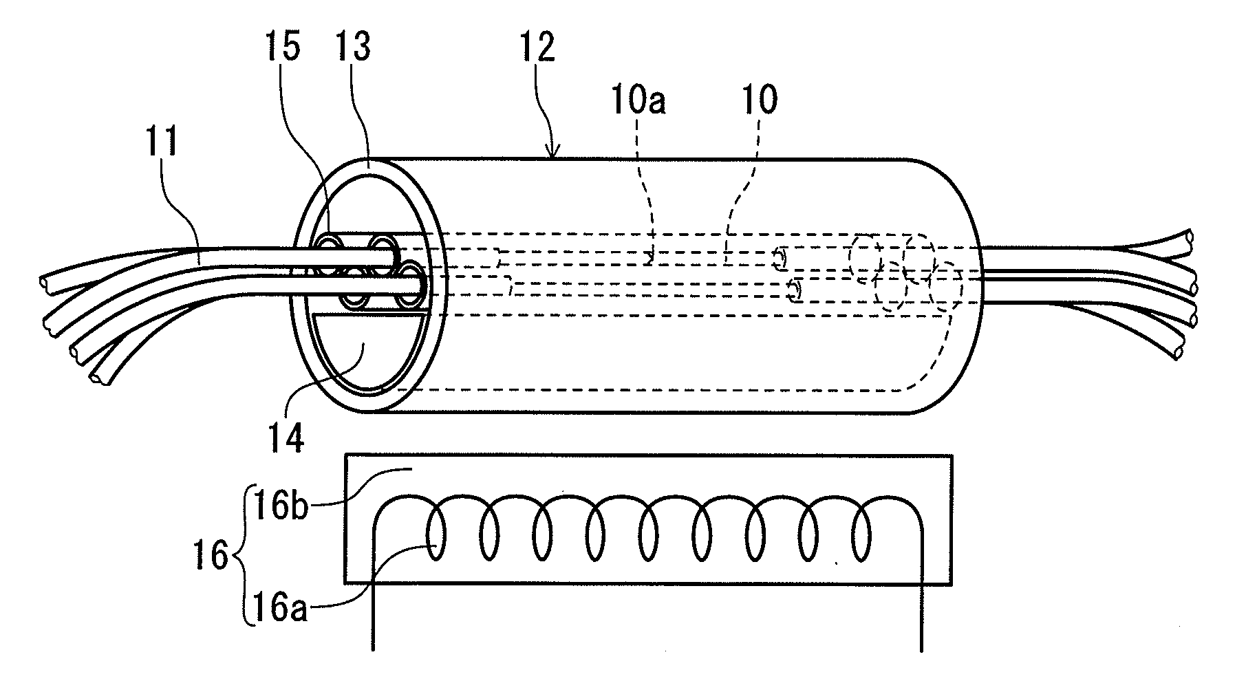
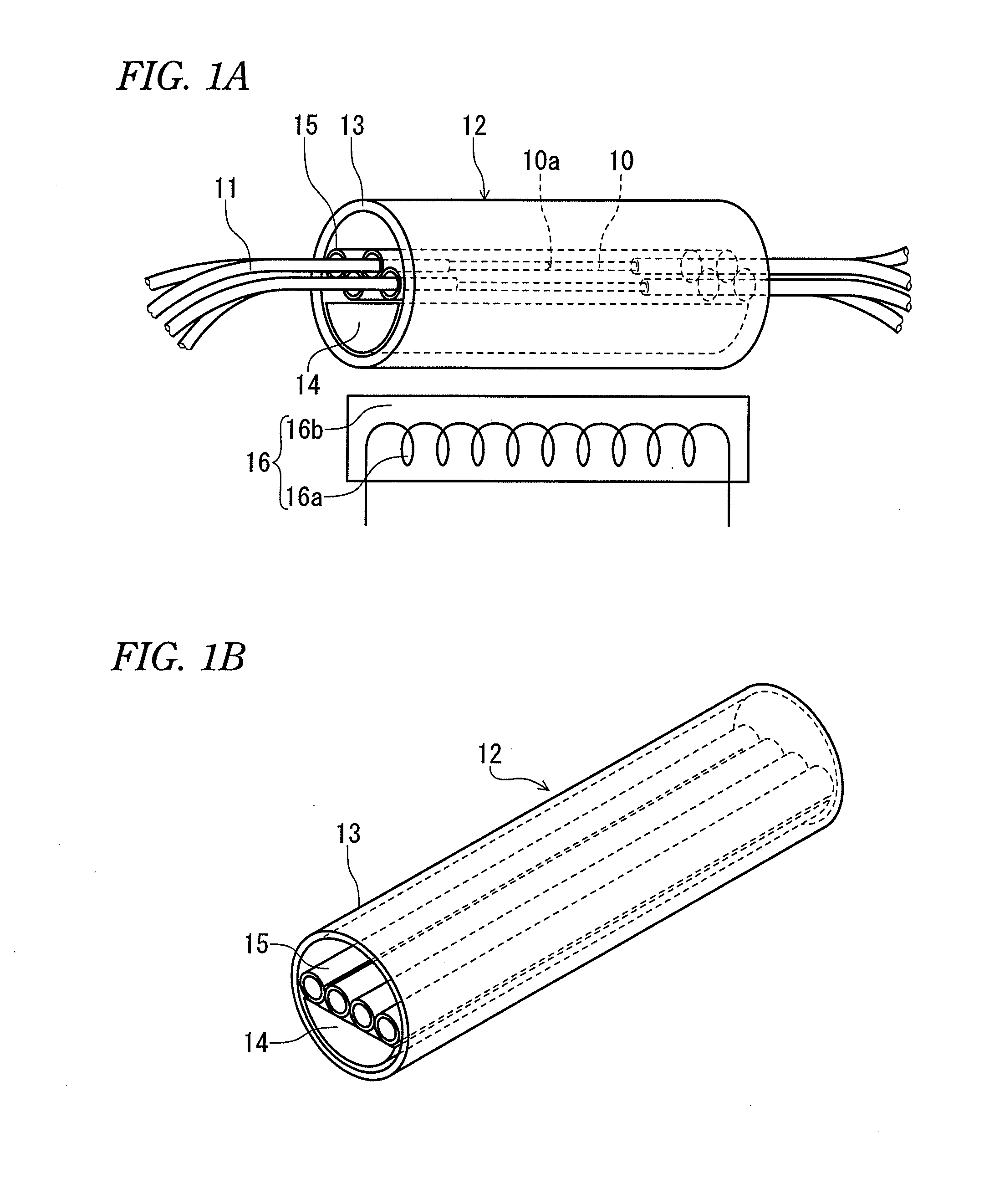
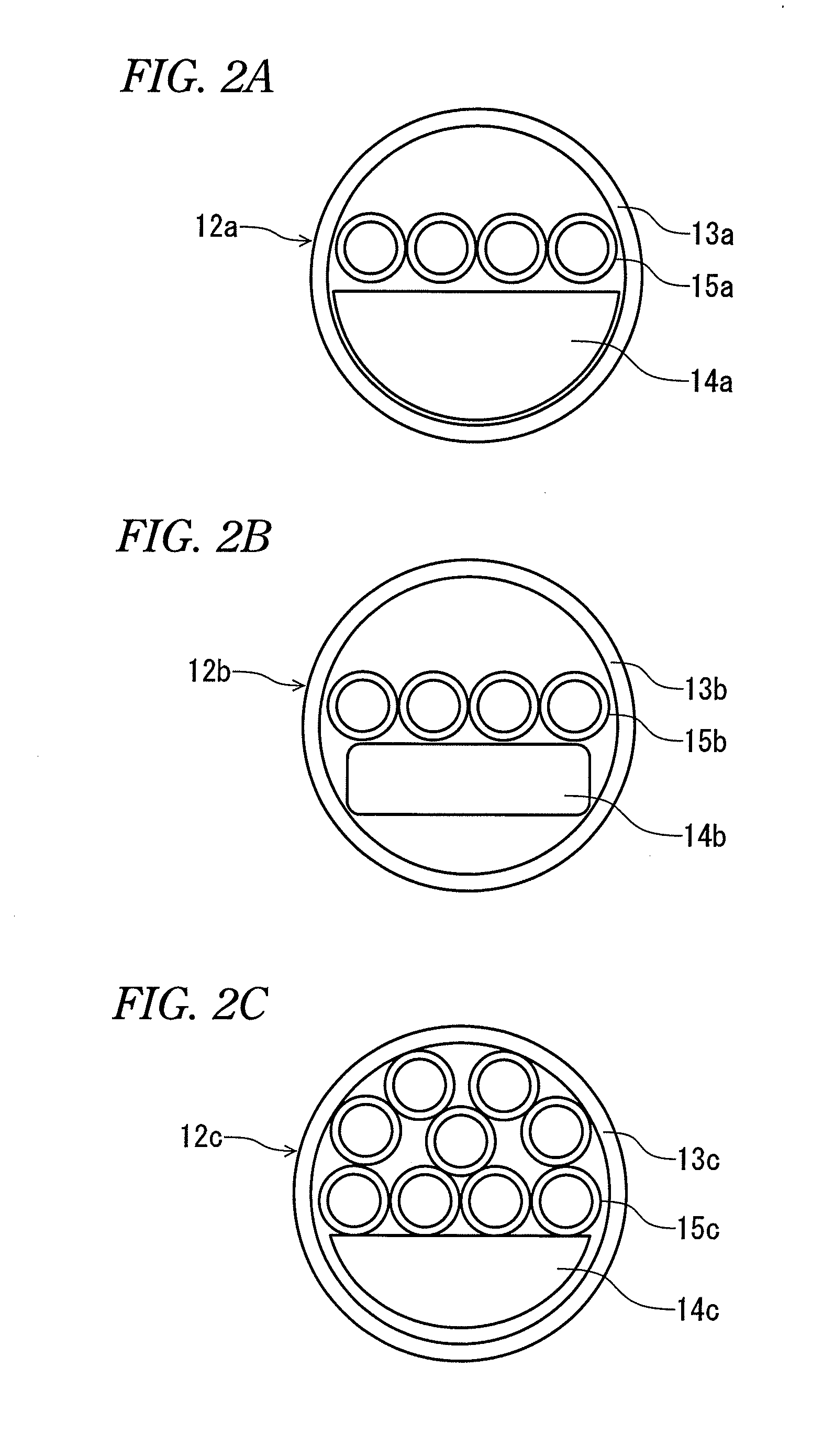
[0017]With reference to drawings, embodiments of the invention will be described. In the drawings, a reference numeral 10 represents a glass fiber portion, 10a represents a fusion-splicing portion, 11 represents a coated optical fiber, represents reinforcing member, 13 represents a heat-shrinkable tube, 14 represents a tensile strength body, 15 represents a tube-shaped heat-fusible adhesive member, 16 represents a heater, 16a represents a heater wire, 16b represents a heater platform.

[0018]Fusion-splicing of optical fibers is performed, as shown in FIG. 1A, by removing fiber coating of an end portion to be connected of each coated optical fiber 11 thereby to expose the glass fiber portion 10 thereof, coupling the end portions of the exposed glass fiber portions 10 to each other, and melting the abutting end portions with heat. The fusion-splicing glass fiber portions 10 where the fiber coatings are removed exhibit a weak mechanical strength, including the fusion-splicing portion 10a...


PUM


Abstract

A reinforcing member of optical fiber fusion-splicing portion and a reinforcing method thereof are provided, in which plural coated optical fibers can be collectively reinforced in the high density, and a heating mechanism for collective reinforcement can be configured at a low cost.A reinforcing member 12 which reinforces collectively fusion-splicing portions 12a of plural coated optical fibers 11 includes a heat-shrinkable tube 13, a rod-shaped tensile strength member 14 arranged so that a part of its surface comes into contact with an inner surface of the heat-shrinkable tube, and plural tube-shaped heat-fusible adhesive members 15 arranged in the heat-shrinkable tube and into which the fusion-splicing portions of the single-core coated optical fibers are individually inserted. All of the plural tube-shaped heat-fusible adhesive members 15 are arranged in one of space portions formed between the tensile strength body 14 and the heat-shrinkable tube.

Description

TECHNICAL FIELD[0001]The present invention relates to a reinforcing member for collectively reinforcing, as a single body, a plurality of coated optical fibers which have been individually fusion-spliced, and to a reinforcing method using the reinforcing member.BACKGROUND ART[0002]Optical fibers are fusion-spliced to each other by removing fiber coatings of end portions to be fusion-spliced of the optical fibers, and heating and fusing end portions of the exposed glass fiber portions to fusion-splice their end portions. The glass fiber portions fusion-spliced to each other, where the fiber coatings are removed, are weak in mechanical strength, and therefore are protected and reinforced by a reinforcing member. This reinforcing member is usually formed by accommodating a rod-shaped tensile strength body and a tube-shaped heat-fusible adhesive member in a heat-shrinkable tube which shrinks radially by heating.[0003]Further, by the development of an optical communication network, many ...

Claims


Application Information

Patent Timeline
Patent Type & Authority Applications(United States)
IPC IPC(8): G02B6/255
CPCG02B6/2558G02B6/255
Inventor SATO, RYUICHIROTOYOOKA, HIROYASUHOMMA, TOSHIHIKOMURASHIMA, KIYOTAKA
Owner SUMITOMO ELECTRIC IND LTD
Why Eureka
Try Eureka