Optical measuring device with positional displacement detection

a technology of optical measuring device and positional displacement, which is applied in the field of optical measuring device with positional displacement detection, can solve the problems of difficult to move the measurement object toward the focused position, the measurement object cannot be correctly detected at the edge position, and the measurement object cannot be determined whether it is possible to focus on the position, so as to improve the accuracy of position measurement and correct the inclination of the edge. , the effect of simple configuration

Active Publication Date: 2015-06-30
KEYENCE
View PDF8 Cites 10 Cited by
  • Summary
  • Abstract
  • Description
  • Claims
  • Application Information

AI Technical Summary

Benefits of technology

[0011]An object of the present invention is to provide an optical measuring device capable of easily improving accuracy in measurement of a measurement object.

Problems solved by technology

In this case, it may not be possible to correctly detect the edge position of the measurement object.
However, it is not possible to determine whether the measurement object is on a side of the focused position closer to the light projecting unit, or on a side of the focused position away from the light projecting unit.
In this case, it is difficult to move the measurement object toward the focused position.
Therefore, it is not easily to improve accuracy in measurement of the edge position of the measurement object.

Method used


Image

  • Optical measuring device with positional displacement detection
  • Optical measuring device with positional displacement detection
  • Optical measuring device with positional displacement detection

Examples


first embodiment

[1] First Embodiment

[0058](1) Configuration of Optical Measuring Device

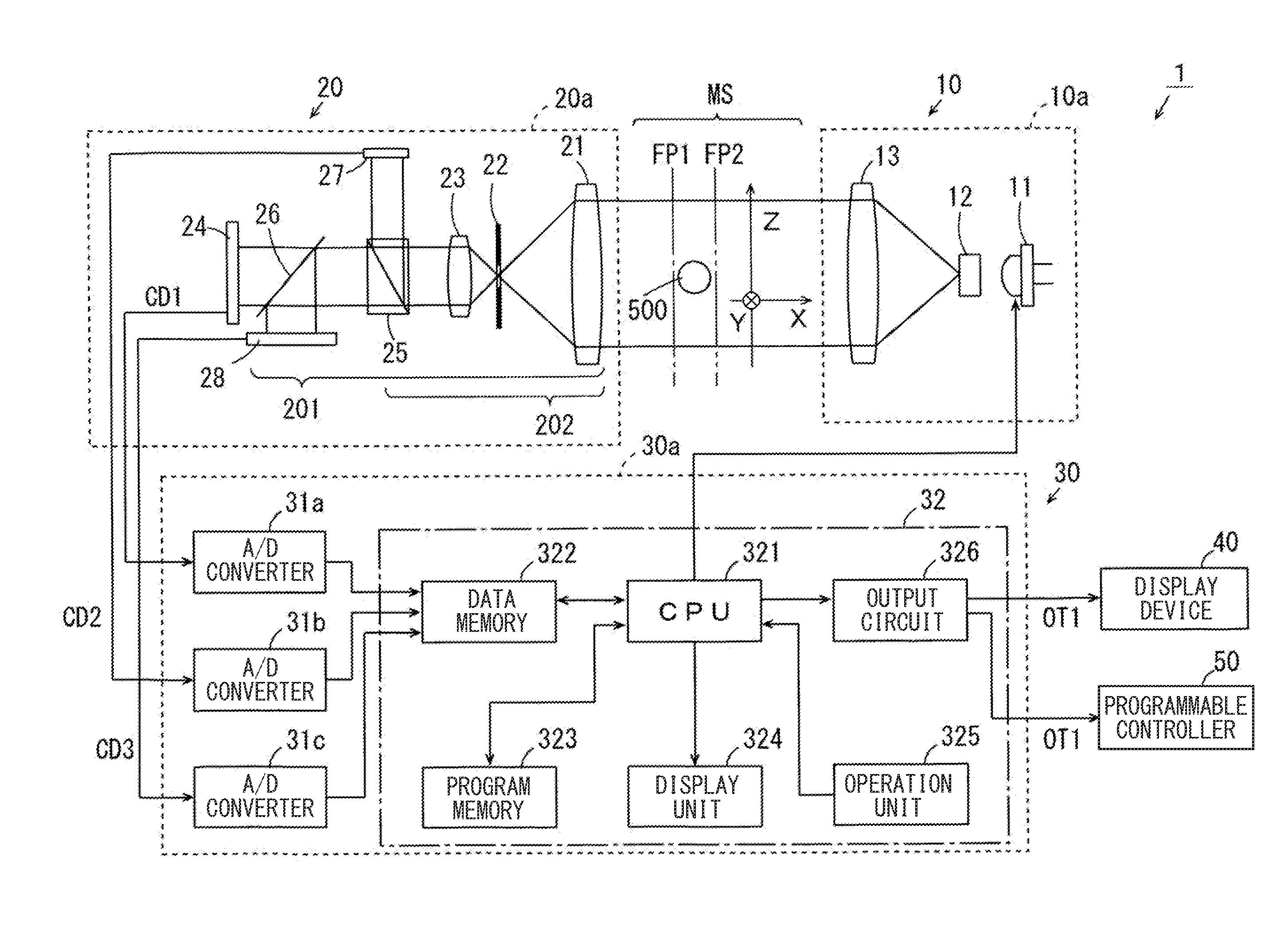
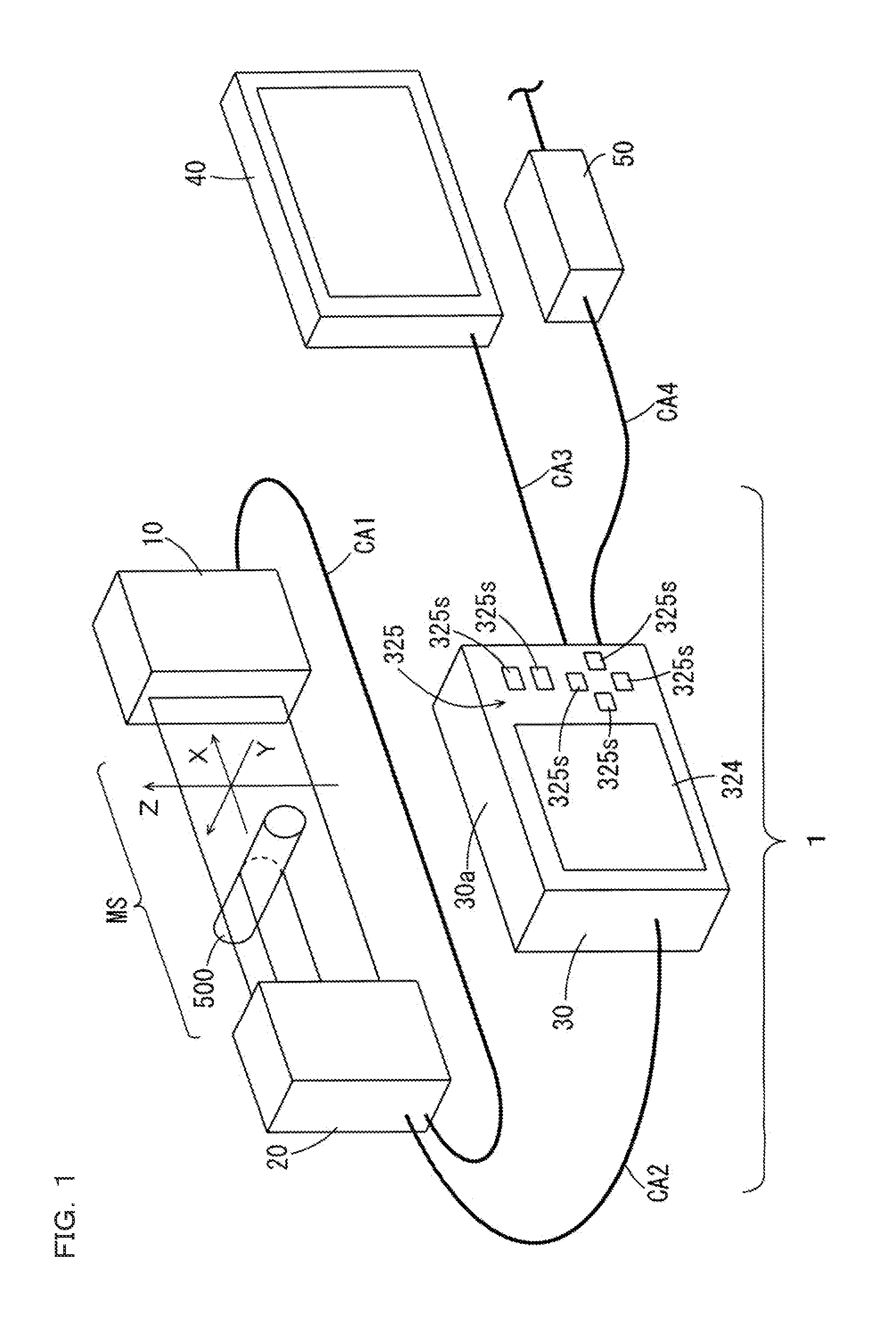
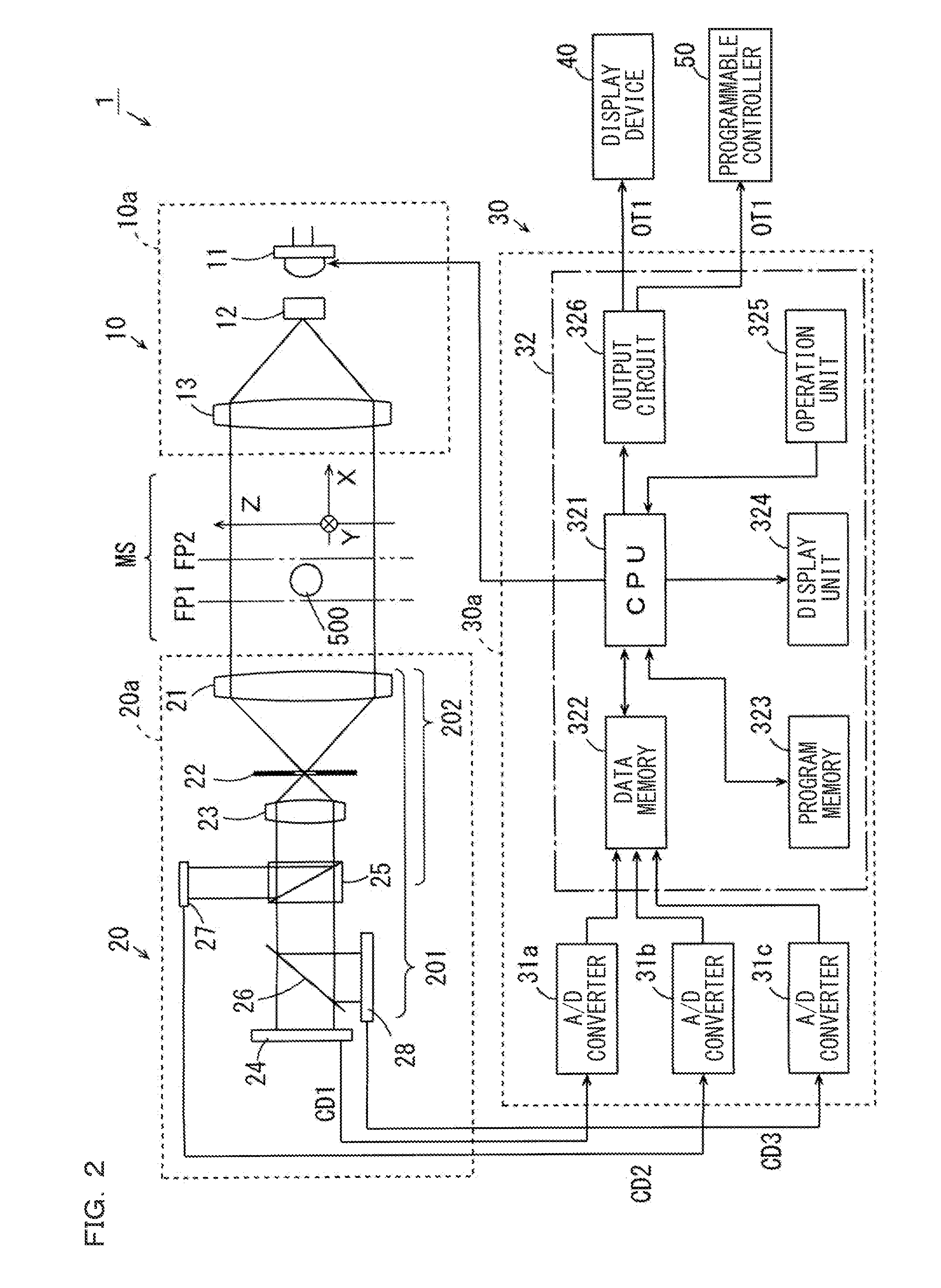
[0059]Hereinafter, an optical measuring device according to a first embodiment will be described with reference to the drawings. FIG. 1 is an external perspective view of the optical measuring device according to the first embodiment, and FIG. 2 is a block diagram showing a configuration of the optical measuring device according to the first embodiment.

[0060]An optical measuring device 1 according to the first embodiment is provided with a light projecting unit 10, a light receiving unit 20, and a controller 30. As shown in FIG. 1, the light projecting unit 10 and the light receiving unit 20 are connected to each other via a cable CA1. Further, the light receiving unit 20 and the controller 30 are connected to each other via a cable CA2. Various signals are transmitted between the light projecting unit 10, the light receiving unit 20, and the controller 30 via the cables CA1 and CA2. Further, the controller 30 is...

second embodiment

[2] Second Embodiment

[0183]FIG. 15 is a block diagram showing a configuration of an optical measuring device 1 according to a second embodiment. As shown in FIG. 15, in the optical measuring device 1 according to this embodiment, the light receiving unit 20 is not provided with the beam splitter 25 and the second image sensor 27 of FIG. 2, and the controller 30 is not provided with the A / D converter 31b of FIG. 2.

[0184]In the third image sensor 28, part of pixels arranged along the width direction of the collimated light directed from the second lens 23 and the half mirror 26 out of the plurality of pixels arranged two-dimensionally serve as the second image sensor 27 in the first embodiment. With this, in the measurement space MS, a focus of a third optical system 203 corresponding to the third image sensor 28 is positioned as the second focus FP2 at a position displaced from the first focus FP1. In this embodiment, an optical path from the first lens 21 to the third image sensor 2...


PUM


Abstract

Provided is an optical measuring device capable of easily improving accuracy in measurement of a measurement object. Light is projected from a light projecting unit into a measurement space. Light passing through the measurement space is directed toward a first image sensor through a first optical system, and directed toward a second image sensor through a second optical system. Within the measurement space, a position of a first focus of the first optical system and a position of a second focus of the second optical system in an X direction are different from each other. Whether the measurement object is positioned at the first focus, on a side of the first focus closer to the light projecting unit, or on a side of the first focus away from the light projecting unit is determined based on the signals outputted from the first and the second image sensor.

Description

CROSS-REFERENCE TO RELATED APPLICATIONS[0001]The present application claims foreign priority based on Japanese Patent Application No. 2012-141532, filed Jun. 25, 2012, the contents of which is incorporated herein by reference.BACKGROUND OF THE INVENTION[0002]1. Field of the Invention[0003]The present invention relates to an optical measuring device which irradiates a measurement object with light and measures a light amount distribution of light transmitted through or reflected on the object.[0004]2. Description of Related Art[0005]Conventionally, there has been used an optical measuring device configured to measure dimensions of an object, an interval between objects, a position of an object, a shape of an object, and the like by irradiating the object with light from a light source and by measuring a light amount distribution of light transmitted through or reflected on the object.[0006]According to the optical measuring device described in JP 2002-277211 A, light emitted from a l...

Claims


Application Information

Patent Timeline
Patent Type & Authority Patents(United States)
IPC IPC(8): G01B11/14G01B11/10G01B11/02
CPCG01B11/14G01B11/105G01B11/026
Inventor FUJIMOTO, TAKASHI
Owner KEYENCE
Why Eureka
Try Eureka