Display control apparatus and display control method
a control apparatus and display technology, applied in the field of display control apparatus and method, can solve the problems of consuming power, affecting operation, and affecting the operation of the display, so as to prevent the effect of turning off the touch panel and impairing the operation
- Summary
- Abstract
- Description
- Claims
- Application Information
AI Technical Summary
Benefits of technology
Problems solved by technology
Method used
Image
Examples
first embodiment
[0051][First Embodiment]
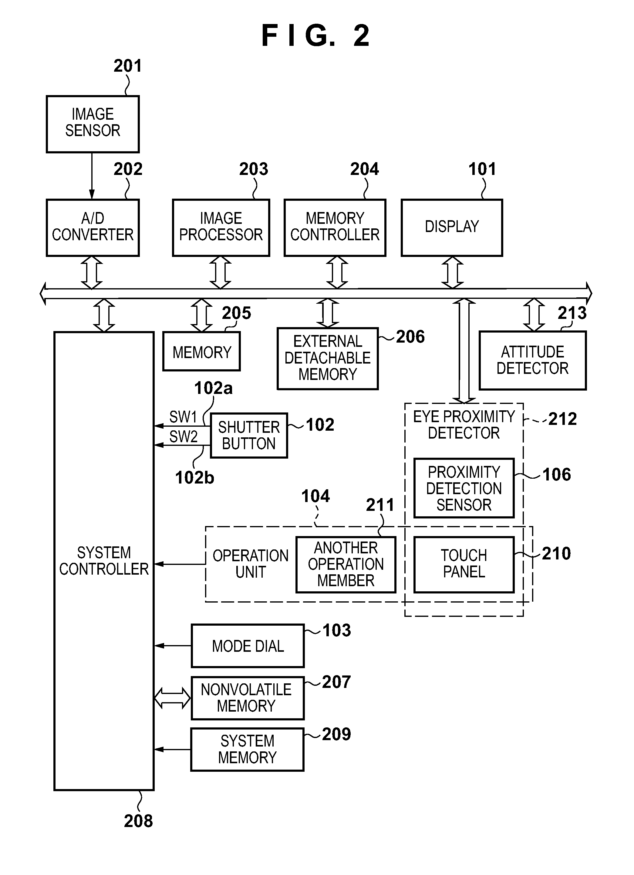
[0052]Display control processing in the first embodiment based on eye proximity detection using a proximity detection sensor and the proximity detection function of a touch panel will be described with reference to FIG. 4. Note that the processing shown in FIG. 4 is implemented by expanding, in a system memory 209, a program stored in a nonvolatile memory 207 and executing it by a system controller 208.
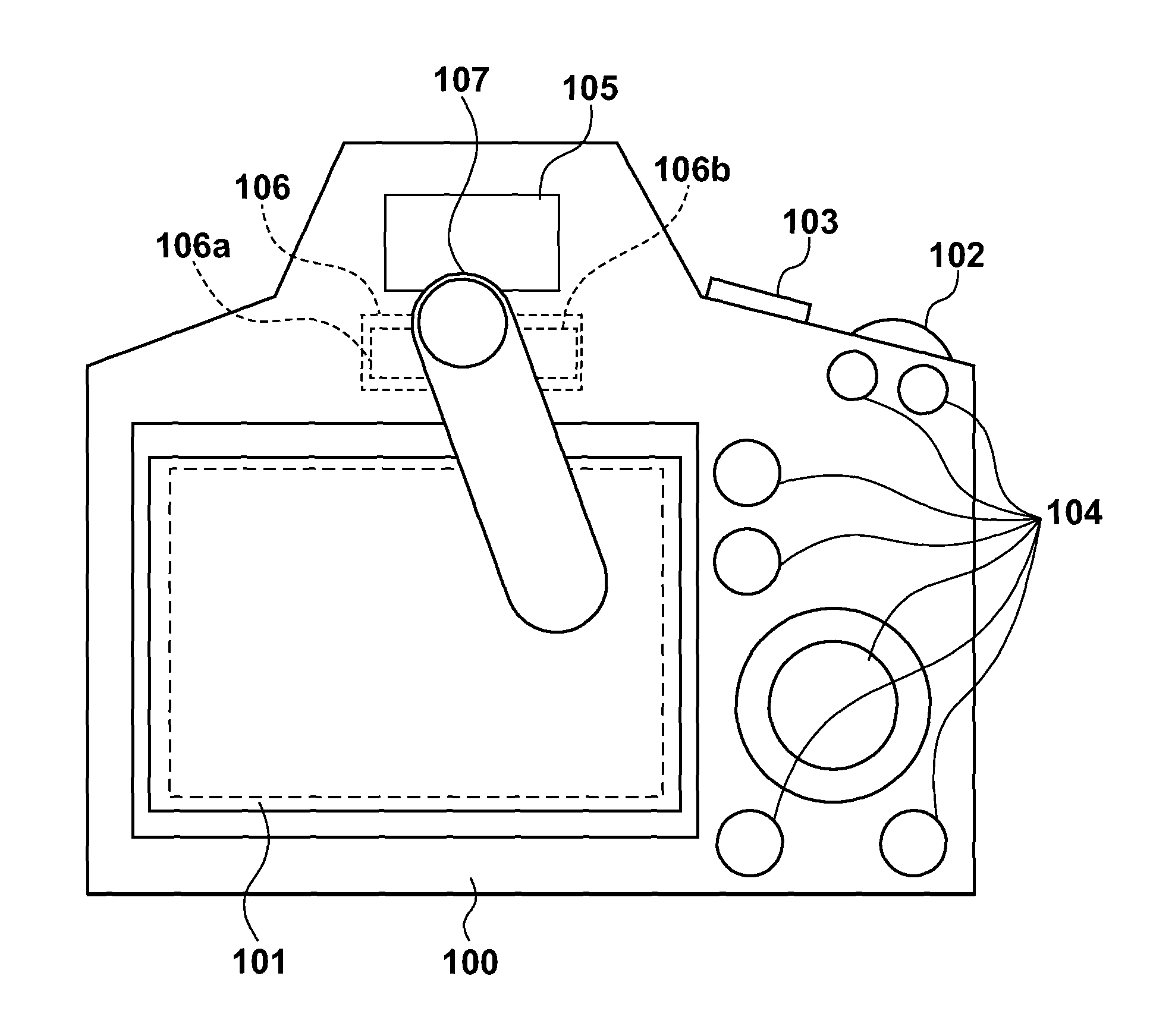
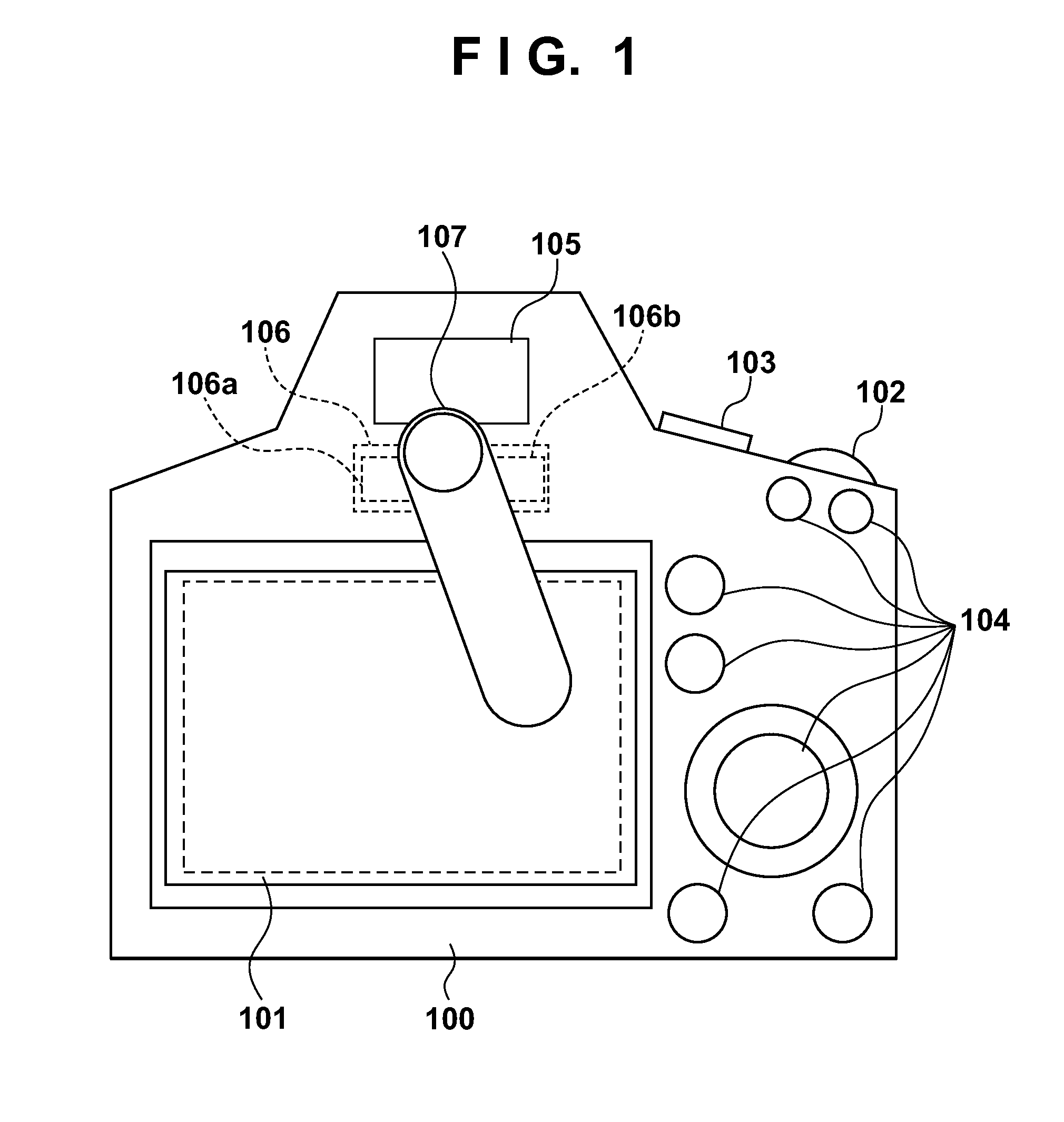
[0053]In step S401 of FIG. 4, the system controller 208 determines whether an object 107 to be detected has come close. If a light amount equal to or larger than a threshold is detected in a light-receiving lens window 106b of a proximity detection sensor 106, the system controller 208 determines that the object 107 to be detected has come close, and the process shifts to step S402. If no such light amount is detected, the system controller 208 determines that the object 107 to be detected has not come close, and the process returns to step S401.
[0054]In step S...
second embodiment
[0063][Second Embodiment]
[0064]Display control processing in the second embodiment in which the detection region of a touch panel is changed in accordance with the attitude of an image capturing apparatus will be described with reference to FIG. 5. In the second embodiment, processing in the first embodiment is executed at higher precision by changing the detection region of the touch panel in accordance with the attitude of the image capturing apparatus. Note that the processing shown in FIG. 5 is implemented by expanding, in a system memory 209, a program stored in a nonvolatile memory 207 and executing it by a system controller 208.
[0065]Steps S501 and S505 to S508 in FIG. 5 are the same processes as those in steps S401 and S403 to S406 in FIG. 4, and a description thereof will not be repeated.
[0066]In step S502, the system controller 208 controls an attitude detector 213 to determine which of the landscape position and portrait position is the attitude of an image capturing appa...
third embodiment
[0071][Third Embodiment]
[0072]Display control processing in the third embodiment in which the detection region of a touch panel is changed in accordance with the dominant eye will be described with reference to FIG. 7. In the third embodiment, processing in the first embodiment is executed at higher precision by changing the detection region of the touch panel in accordance with the dominant eye setting. Note that the processing shown in FIG. 7 is implemented by expanding, in a system memory 209, a program stored in a nonvolatile memory 207 and executing it by a system controller 208.
[0073]Steps S702 and S706 to S709 in FIG. 7 are the same processes as those in steps S401 and S403 to S406 in FIG. 4, and a description thereof will not be repeated.
[0074]In step S701 of FIG. 7, if dominant eye information is set by a user operation, the system controller 208 stores the set dominant eye information in the nonvolatile memory 207.
[0075]In step S703, the system controller 208 determines th...
PUM
 Abstract
Description
Claims
Application Information
 - R&D
- Intellectual Property
- Life Sciences
- Materials
- Tech Scout
- Unparalleled Data Quality
- Higher Quality Content
- 60% Fewer Hallucinations
Browse by: Latest US Patents, China's latest patents, Technical Efficacy Thesaurus, Application Domain, Technology Topic, Popular Technical Reports.
© 2025 PatSnap. All rights reserved.Legal|Privacy policy|Modern Slavery Act Transparency Statement|Sitemap|About US| Contact US: help@patsnap.com


