Connecting System and Constant Velocity Joint

Active Publication Date: 2012-03-08
SHAFT FORM ENG GMBH
View PDF6 Cites 3 Cited by
  • Summary
  • Abstract
  • Description
  • Claims
  • Application Information

AI Technical Summary

Benefits of technology

[0008]Another object of the invention is to provide a system for connecting a shaft to a joint, which system firstly protects the shaft from being pressed past its intended position during the assembly operation or during operation and which ensures a secure positioning of the retaining ring.
[0009]A further object of the invention is to provide a system for connecting a shaft to a joint which system also simultaneously exhibits improvements in terms of its weight, installation space and ease of assembly.
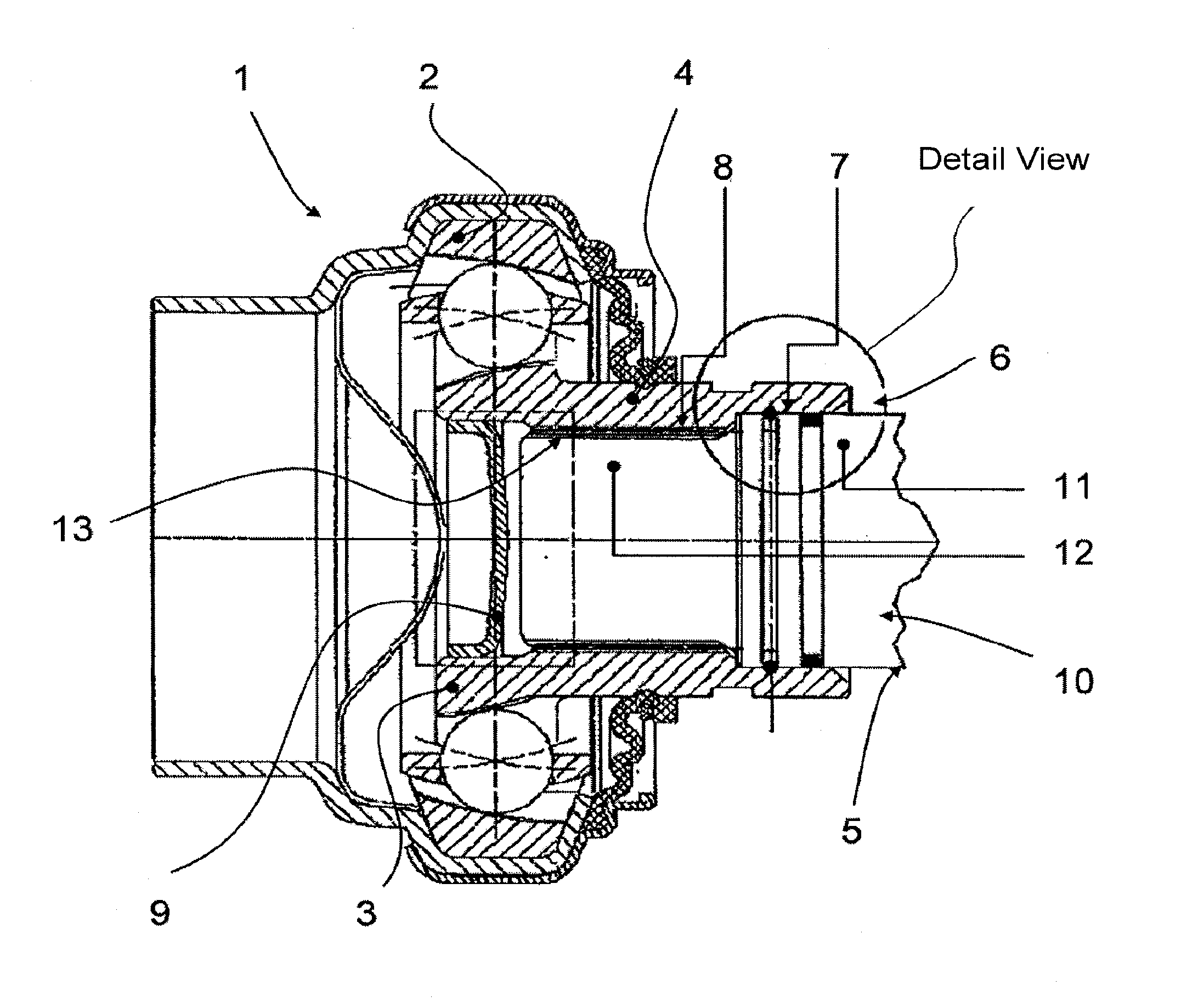
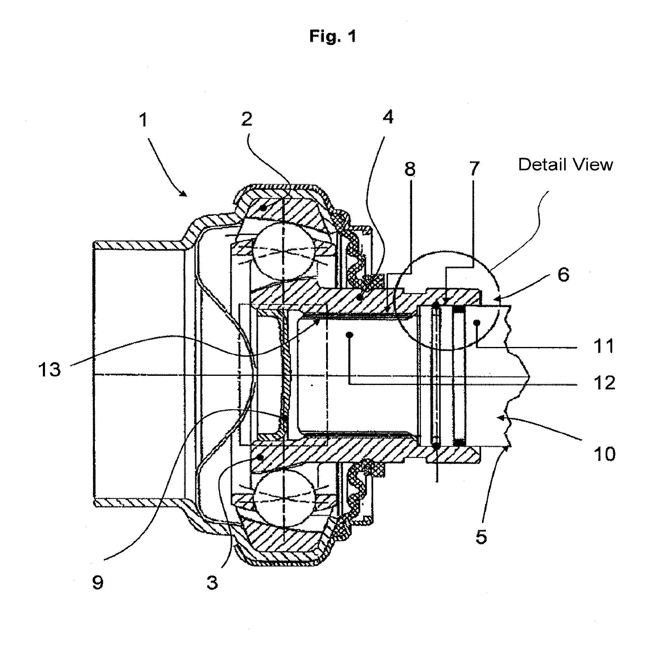
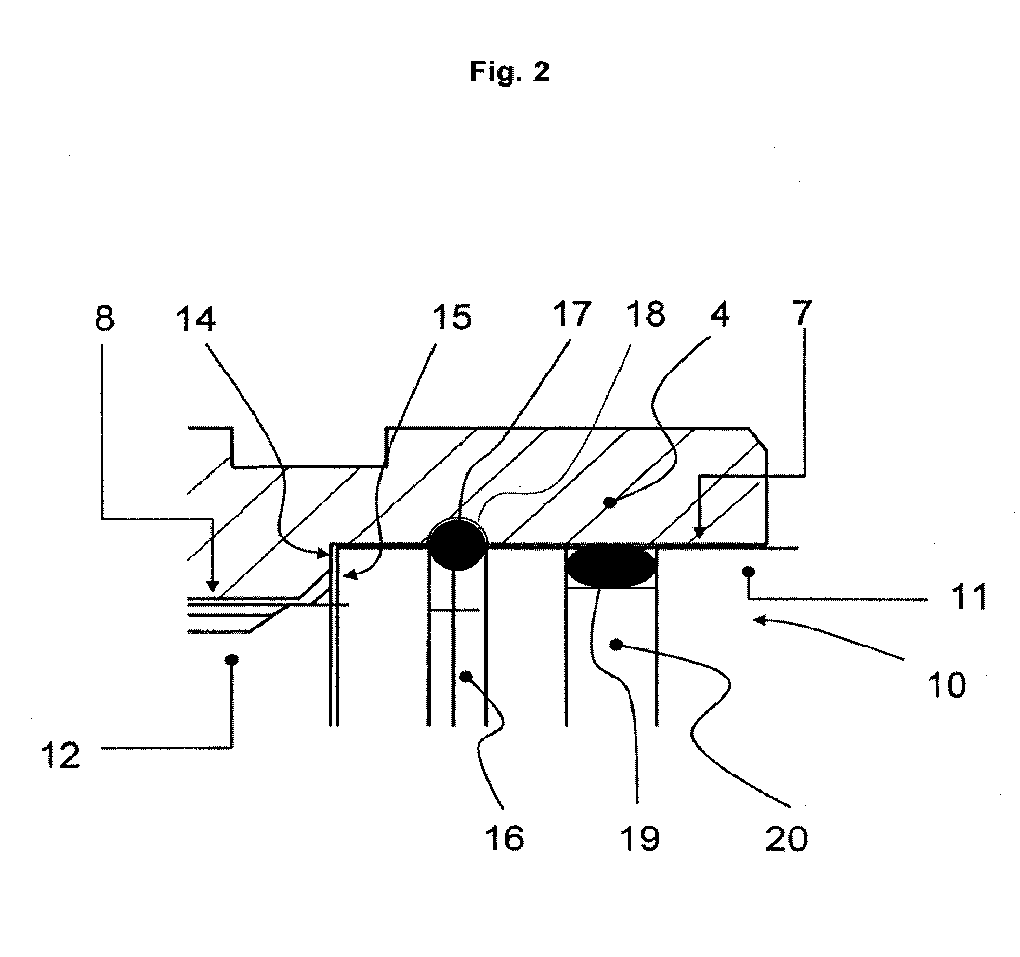
[0010]According to the invention, these and other objects of the invention are achieved substantially in that the sleeve comprises a central opening comprising a shaft-side first opening section, the internal diameter of which is larger than that of a joint-side second opening section disposed in the direction of insertion, a first radial stop section being provided between the first opening section and the second opening section. This first radial stop section extends at least substantially at right angles to the longitudinal axis of the sleeve. Similarly, the shaft journal comprises a shaft-side first shaft-journal section, the external diameter of which is larger than that of a joint-side second shaft-journal section, a second radial stop section being provided between the first shaft-journal section and the second shaft-journal section in the form of a counter-stop for delimiting the insertion path of the shaft journal in the sleeve. Likewise, this second radial stop section extends at least substantially at right angles to the longitudinal axis of the shaft journal. When, for example, the shaft journal, which may be formed integrally with the shaft, is inserted into the opening of the sleeve, the shaft journal and the sleeve are secured against axial relative movements by the retaining ring that engages in a peripheral groove on the shaft journal and simultaneously in an inner groove on the inner surface of the sleeve. In the case of excessively high axial loads, such as those that can occur, for example, during an incorrectly carried out assembly operation, this axial retainer is not over-pressed since the second stop section of the shaft journal abuts against the first stop section of the opening section. Thus the insertion path of the shaft journal in the sleeve is always delimited by the stop sections, and the shaft journal cannot penetrate the interior of the joint. In this way, it is always ensured that the retaining ring is in its correct position. Moreover, the assembly can be carried out in a single operation since the shaft journal need only be inserted into the opening and secured axially by automatically locking the retaining ring. The stop ensures the correct orientation of the peripheral groove of the shaft journal relative to the inner groove of the sleeve and the engagement of the retaining ring in the grooves. As compared to connection systems known in the prior art, the arrangement of the securing mechanism in the opening of the sleeve provides the option of realizing a space-saving and light-weight solution.
[0012]It has proven to be advantageous if the shaft journal comprises a sealing ring that is configured to seal the sleeve. During regular operation, the drive train of a motor vehicle is exposed to harmful environmental effects such as salt, water, sand etc. which can impair the operability of a joint in that, for example, the lubricating grease becomes contaminated and results in increased friction. The sealing ring seals the constant velocity joint from such types of harmful elements so that these harmful substances cannot enter the interior of the joint, more particularly, the region of the splines. This also serves to protect the splines from dirt and corrosion during assembly and disassembly. Advantageously, this sealing ring is disposed on the shaft-side upstream of the retaining ring. In principle, however, it is also possible to arrange the sealing ring on the joint-side second shaft-journal section, as a result of which the interior of the joint continues to be protected from environmental effects.
[0016]Particularly with a view to reducing parts and saving weight, provision is made in an additional embodiment of the invention for a sleeve that is formed integrally with the inner hub. Furthermore, the joint opening can be closed by a cover on the side oriented away from the shaft, which reduces the requirement of lubricant in the interior of the joint. The second shaft-journal section is configured such that the shaft journal does not impact against the cover, as a result of which the lubricant supply system in the joint remains protected from harmful effects. More particularly, the second shaft journal is prevented from contacting the cover by delimiting the insertion path of the shaft journal in the sleeve by the corresponding stop sections.

Problems solved by technology

When the shaft journal in this joint is secured only by a retaining ring, there is a risk that the shaft journal can no longer be held by the retaining ring in the case of extremely high insertion forces and the shaft journal may impact against the cover due to the high applied force and push the cover out of its mounting, thereby causing a possible leakage of lubricant and / or entry of dirt particles.
As a result of the external flange extending from the shaft outwardly in the radial direction, such a solution for the connection system necessitates a large amount of space and, at the same time, increased weight and material, which conflicts with the general requirement of reducing weight, costs, fuel consumption, and CO2 emission.
Furthermore, the shaft must first be inserted into the joint connection, and then a suitable means for axially securing the shaft must be applied, as a result of which the assembly effort increases and an automatic assembly proves to be more difficult.

Method used


Image

  • Connecting System and Constant Velocity Joint
  • Connecting System and Constant Velocity Joint
  • Connecting System and Constant Velocity Joint

Examples


Embodiment Construction

[0021]The constant velocity joint 1 shown in FIG. 1 comprises an outer hub 2 and an inner hub 3 that is formed integrally with a sleeve 4. The sleeve 4 is in turn configured to be connected to a drive shaft 5 or to a shaft to be driven. For this purpose, the sleeve 4 comprises an opening 6 comprising a shaft-side first opening section 7 and a joint-side second opening section 8. The interior of the constant velocity joint 1 is sealed from the opening 6 of the sleeve 4 by a cover 9 that is inserted into the sleeve 4.

[0022]On the joint side, the shaft 5 ends in a shaft journal 10 comprised of a shaft-side first shaft-journal section 11 and a joint-side second shaft-journal section 12. In FIG. 1, the shaft 5 together with the shaft journal 10 is shown as being disposed in the opening 6 of the sleeve 4 which corresponds to the state after assembly; i.e. the state in which the shaft journal 10 has been inserted into the opening 6 of the sleeve 4. As a result of this insertion, the shaft-...


PUM


Abstract

A system for connecting a shaft (5) to a joint (1), which system includes a shaft journal (10) that is connected to the shaft (5), and a sleeve (4) that is connected to a hub of the joint (1), the sleeve (4) having a shaft-side first opening section (7), a joint-side second opening section (8), and a first radial stop section (14), and the shaft journal (10) having a shaft-side first shaft-journal section (11), a joint-side second shaft-journal section (12), and a second radial stop section (15) for delimiting the insertion path of the shaft journal (10) in the sleeve (4).

Description

CROSS REFERENCE TO RELATED APPLICATIONS[0001]This application is a continuation of international patent application No. PCT / DE2010 / 000355, filed Mar. 25, 2010, designating the Unites States of America and published in German on Oct. 21, 2010 as WO 2010 / 118725 A1, the entire disclosure of which is incorporated herein by reference. Priority is claimed based on Federal Republic of Germany patent application no. DE 10 2009 017 007.3, filed Apr. 14, 2009, the entire disclosure of which is likewise incorporated herein by reference.BACKGROUND OF THE INVENTION[0002]The invention relates to a system for connecting a shaft to a joint, which system comprises a shaft journal that is connected to the shaft and a sleeve that is connected to a hub of the joint. The sleeve comprises a central opening for receiving the shaft journal that is secured axially in the sleeve by a retaining ring.[0003]Published German patent application no. DE 197 39 934 discloses a generic connection system in which a tu...

Claims


Application Information

Patent Timeline
IPC IPC(8): F16D3/00F16B17/00F16D3/223F16D3/2237
CPCF16D1/116F16D3/2237F16D2003/22306Y10T403/52Y10T403/7033Y10T403/7075F16D2300/12F16D2003/22313F16D2300/08F16B2200/60
Inventor LANGER, GERALDDISSER, CLAUSSZENTMIHALYI, VOLKER
Owner SHAFT FORM ENG GMBH
Why Eureka
Try Eureka