Disposition zone in an aircraft passenger cabin

a technology for disposing zones and passenger cabins, which is applied in the field of disposing zones in aircraft passenger cabins, can solve the problems of reducing the passenger space of the module, affecting the service life of passengers, and affecting the work efficiency of passengers in business class, so as to improve the services and comfort offered to passengers

Active Publication Date: 2015-07-07
AIRBUS OPERATIONS GMBH
View PDF22 Cites 9 Cited by
  • Summary
  • Abstract
  • Description
  • Claims
  • Application Information

AI Technical Summary

Benefits of technology

[0006]It is the objective of the present invention to improve the services and comfort offered to the flight passengers by utilizing the space in the passenger cabin or the door entry area that is otherwise not used while cruising.

Problems solved by technology

The floor space required for the module disadvantageously reduces the passenger space.
The working conditions in Business Class seats are frequently restricted due to the space conditions.
Working effectively is impossible in the Tourist Class, wherein the background noise caused by fellow passengers is also distracting.
Another disadvantage in both classes is that confidential documents being worked on are not protected from the prying eyes of fellow travelers.
In passenger cabins of airplanes, the available space is relatively limited for economical reasons.
The disadvantage of conventional cabins is that a relatively large space which is only used briefly in comparison with the total time spent by passengers in the passenger cabin needs to be made available for the predominantly separated entry areas.

Method used


Image

  • Disposition zone in an aircraft passenger cabin
  • Disposition zone in an aircraft passenger cabin
  • Disposition zone in an aircraft passenger cabin

Examples


Embodiment Construction

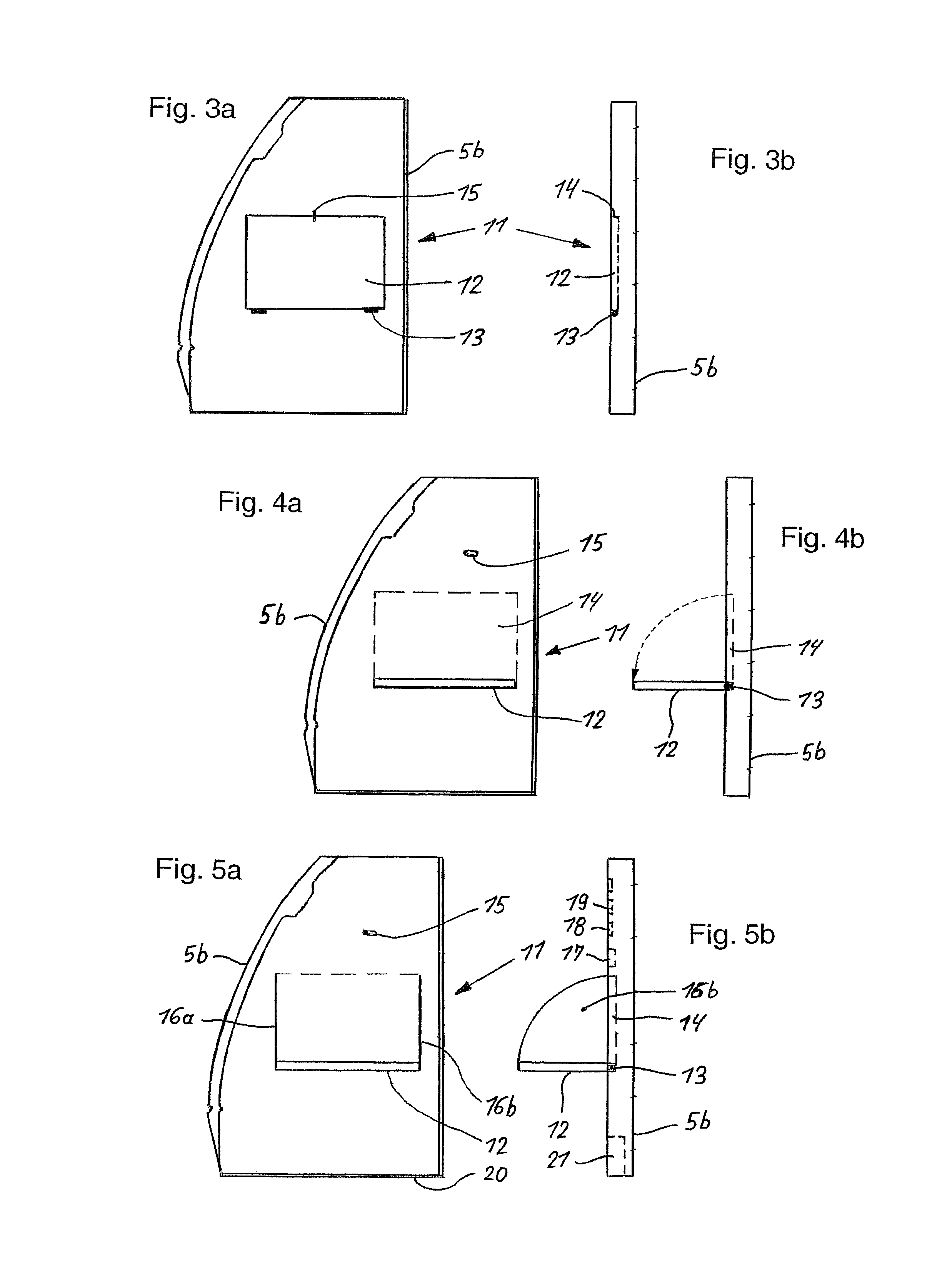
[0049]In the description of FIGS. 1 to 11d, analogous or corresponding components and elements are at least in part identified by the same reference symbols. Furthermore, the uniform term space unit is used for the door entry area and door exit area of the passenger cabin.

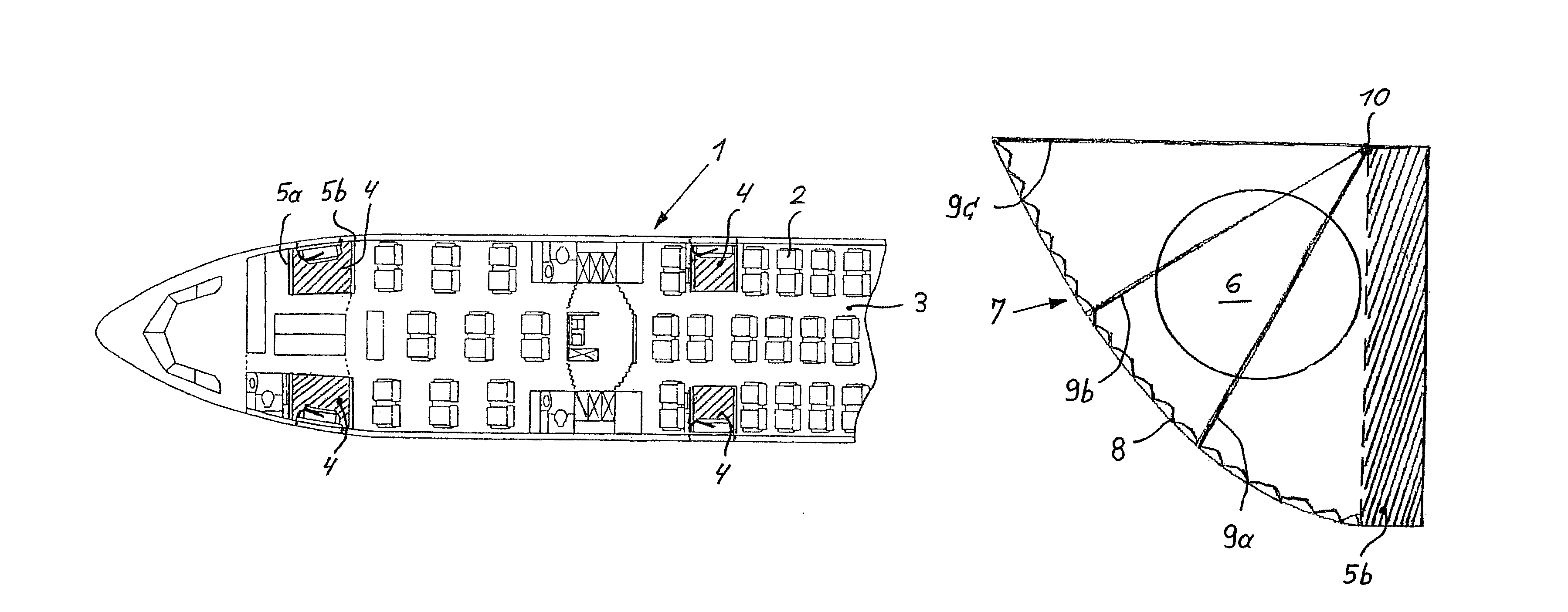
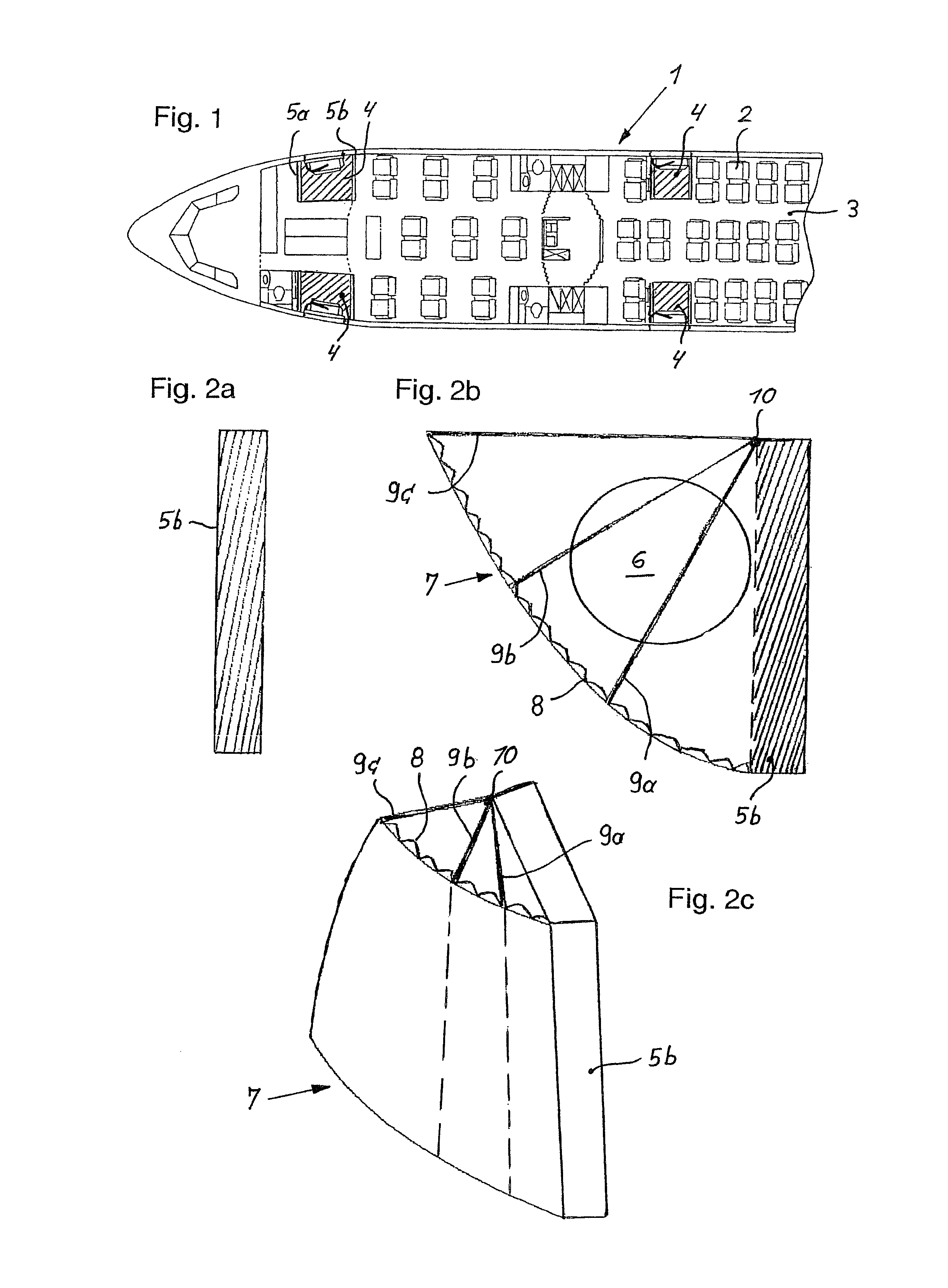
[0050]FIG. 1 shows the design of a section of an aircraft 1 in the form of a sectional representation and elucidates the seat layout of passenger seats 2 in a passenger cabin 3, as well as the arrangement or distribution of the door entry and door exit areas that are referred to as space units 4 and respectively illustrated in a hatched fashion. According to the invention, the space units 4 form disposition zones that can be used for different service and / or comfort facilities and also referred to as Working Areas. In this case, the space units 4 are laterally bounded by partition walls 5a, 5b that extend from a cabin floor up to a cabin ceiling.

[0051]FIGS. 2a to 2c show the design and the arrangement of a calling ...


PUM


Abstract

The invention pertains to an aircraft with at least one passenger cabin that comprises at least one door entry area for the passengers and for the flight attendants that is visually separated from the passenger cabin and referred to as a space unit. Variable or mobile elements assigned to at least one partition wall / one monument of the space element can be arranged in the space unit that can be used as a disposition zone during the flight phase in order to realize working areas or service and / or comfort facilities for passengers or for the flight attendants.

Description

CROSS-REFERENCE TO RELATED APPLICATIONS[0001]This application is a national phase entry under 35 U.S.C. §371 of International Application No. PCT / EP2009 / 058118, filed Jun. 29, 2009, published in German, which claims the benefit of the filing date of German Patent Application No. 10 2008 031 021.2 filed Jun. 30, 2008, and of U.S. Provisional Patent Application No. 61 / 133,458 filed Jun. 30, 2008, the disclosures of which applications are hereby incorporated herein by reference.FIELD OF THE INVENTION[0002]The invention pertains to an aircraft with at least one passenger cabin comprising at least one door entry area or door exit area for the passengers and for the flight attendants that is visually separated from the passenger cabin and referred to as a space unit.TECHNOLOGICAL BACKGROUND[0003]In order to meet the requirements in the context of new developments of aircraft and the demands in the near future, it is necessary to improve the service and the comfort and to equip aircraft, f...

Claims


Application Information

Patent Timeline
Patent Type & Authority Patents(United States)
IPC IPC(8): B64D13/00B64D11/00
CPCB64D11/0023
Inventor MOSLER, MICHAELULBRICH-GASPAREVIC, JOVANBREUER, MATTHIAS
Owner AIRBUS OPERATIONS GMBH
Why Eureka
Try Eureka