
Oven door opening and closing device

a technology for oven doors and which is applied in the field can solve the problems of unsatisfactory loud impact noises, the return force provided by buffers has adverse effects on the closing force, and the buffers cannot completely remove the impact noises, etc., and achieves the effect of accurate reciprocating movement and improved installation and handling of oven door opening and closing devices

Inactive Publication Date: 2015-07-07
ELECTROLUX HOME PROD CORP NV
View PDF27 Cites 9 Cited by
  • Summary
  • Abstract
  • Description
  • Claims
  • Application Information

AI Technical Summary

Benefits of technology

[0005]The oven door opening and closing device according to the present invention comprises one or more hinges, which are connectable to an oven door and to an oven housing. Such hinges realize a predetermined pivoting opening and closing movement of the oven door relative to the oven housing between an open and a closed position, whereby the angle between the open and the closed position is preferably about 90 degree. Moreover, the device comprises at least one closing force generating means for generating a predetermined closing force, which presses the oven door against the oven housing in the closed position of the oven door in order to achieve a desired sealing effect. Furthermore, kinematic means are provided, which are coupled to the hinge and to a moveable element in such a manner, that the predetermined pivoting opening and closing movement of the hinge is converted into a predetermined reciprocating opening and closing movement of the moveable element. The kinematic means are, e.g. of mechanical nature and may comprise a combination of gear and rack, connecting rods, etc. Moreover, the oven door opening and closing device according to the present invention contains at least one damping system. The damping system comprises a damper, e.g. a mechanic, pneumatic or hydraulic damper, for generating a damping force. This damping force counteracts the closing movement of the movable element within a predetermined section or range, which corresponds to a predetermined angle section of the pivoting closing movement of the hinge. Accordingly, the pivoting movement of the oven door is slowed down during its closing movement, preferably about the last 30 degree of the closing movement, in order to eliminate the impact noise.
[0007]Advantageously, one or more hinge housings are provided, which are fixable to the oven housing. Each hinge housing can accommodate a hinge, a kinematic mechanism, a moveable element as well as a damping system. Accordingly, the installation and handling of the oven door opening and closing device according to the present invention is improved. Moreover, the movable element is preferably guided within the hinge housing in order to insure an accurate reciprocating movement.
[0008]According to one aspect of the present invention the damping system comprises a conversion mechanism, which preferably comprises a threaded spindle and a spindle nut. The conversion mechanism partially transforms the reciprocating movement of the moveable element into a rotational movement of a rotary element, whereby a rotary damper, which is preferably arranged at the threaded spindle or at the spindle nut, is used for damping said rotational movement of the rotary element. Accordingly, the speed of the closing movement within the predetermined angle section of the oven door can be adjusted by means of changing the incline of the threads of the spindle and the spindle nut and / or the damping force of the rotary damper. Moreover, it is possible to freely define, adjust and change the predetermined angle section.

Problems solved by technology

However, high closing forces lead to undesirable loud impact noises when closing the oven door.
However, such buffers cannot completely remove the impact noises.
Moreover, the return force provided by a buffer has adverse effects on the closing force and hence on the sealing function realized by the closing force generating means.
Finally, the buffers are arranged at a visible location, which might violate the appearance of the oven.

Method used


Image

  • Oven door opening and closing device
  • Oven door opening and closing device
  • Oven door opening and closing device

Examples


first embodiment

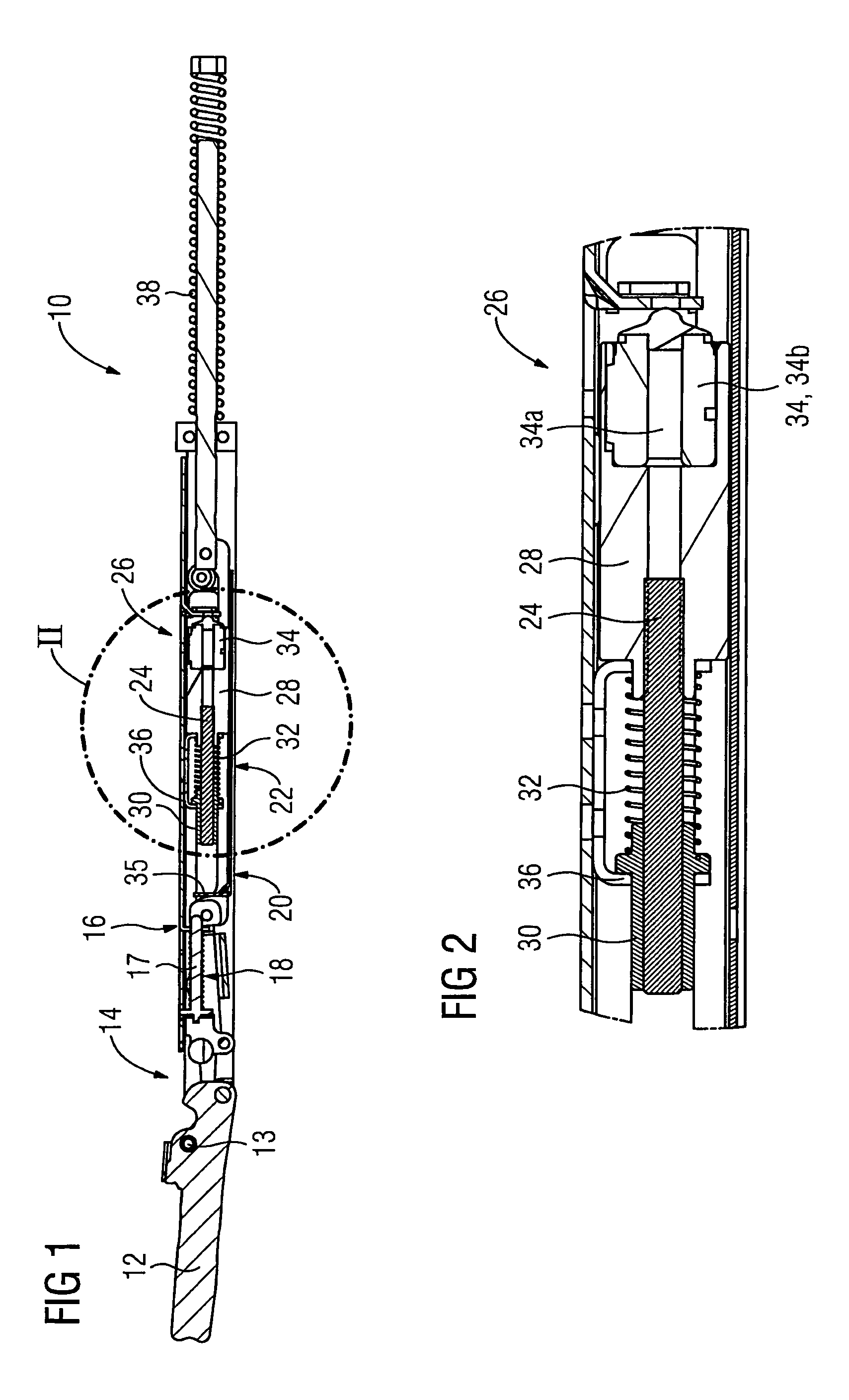
[0032]FIG. 1 is a schematic side view of an oven door opening and closing device 10 according to the present invention, and FIG. 2 is an enlarged view of the section II in FIG. 1. The oven door opening and closing device 10 serves for opening and closing an oven door 12 of an oven, which is not illustrated in the figures. In FIG. 1 the oven door 12 is arranged in its opened position.

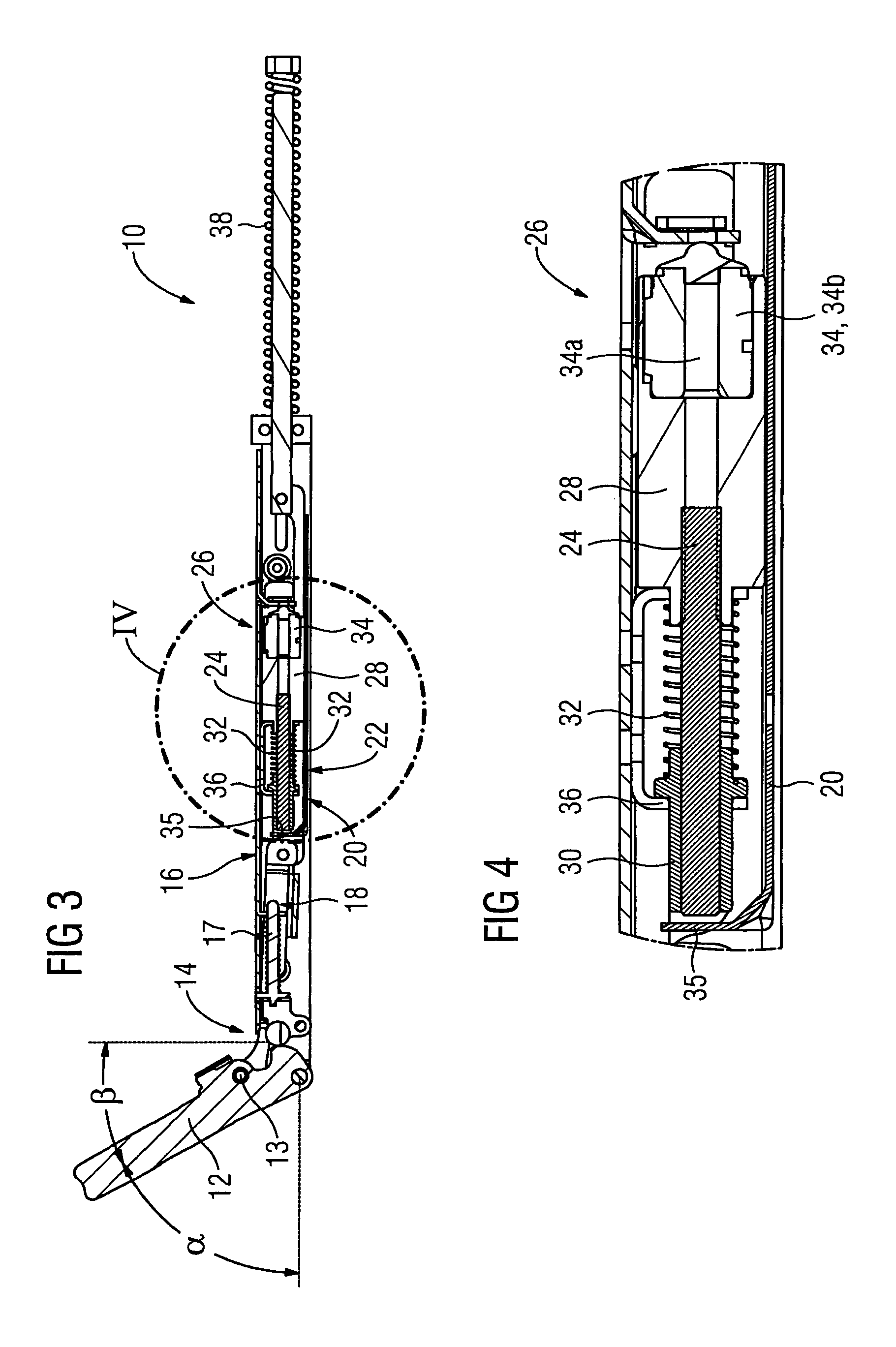
[0033]As main components the oven door opening and closing device 10 comprises a hinge 14, a hinge housing 16, a closing force generating means 17, which forms a part of kinematic means 18, a movable element 20, a conversion mechanism 22, a rotary element 24 and a damping system 26.

[0034]The hinge 14 is fixed to the oven door 12 and to the hinge housing 16 in such a manner that the oven door 12 can perform a predetermined pivoting opening and closing movement around the rotary axis 13 and relative to the oven housing between an open position shown in FIG. 1 and a closed position shown in FIG. 5, whereby ...

second embodiment

[0046]FIG. 7 is a schematic side view of an oven door opening and closing device 40 according to the present invention for opening and closing an oven door 12. Similar to the arrangement shown in FIGS. 1 to 6, the oven door opening and closing device 40 comprises a hinge 14, a hinge housing 16, kinematic means 18, a movable element 42, a conversion mechanism 44, a rotary element 46 and a damping system 48 as main components. The construction of the hinge 14 and the kinematic means 18 essentially corresponds to the one shown in FIGS. 1 to 6. The movable element 42 is formed as a rod, which extends through the hinge housing 16 and is guided therein. Accordingly, the movable element 42 performs a reciprocating linear movement, when the oven door 12 is opened and closed. On the right side of the hinge housing 16 in FIG. 7 the conversion mechanism 44 is arranged, which is provided in form of a rack, which meshes with the rotary element 46, which has the form of a gear. The rotary element...

third embodiment

[0049]FIG. 8 is a schematic side view of an oven door opening and closing device 60 according to the present invention for opening and closing an oven door 12. The oven door opening and closing device 60 essentially corresponds to the device 40 shown in FIG. 7. It comprises a hinge 14, a hinge housing 16, kinematic means 18, a movable element 42 and a damping system 62 as main components. The construction of the hinge 14, the kinematic means 18 and the movable element 42 essentially corresponds to the one shown in FIG. 7. Accordingly, the movable element 42 performs a reciprocating linear movement, when the oven door 12 is opened and closed. An air damper 64 of the damping system 62 is operatively connected to the movable element 42, which at least partially damps the linear closing movement of the movable element 42. Accordingly, the closing movement of the oven door 12 is also damped. As soon as the oven door 12 is opened again, the air damper 64 returns to its initial position.

[0...


PUM


Abstract

An oven door opening and closing device includes at least one hinge connectable to an oven door and to an oven housing for realizing a predetermined pivoting opening and closing movement of the oven door relative to the oven housing between an open and a closed position. At least one closing force generating device generates a predetermined closing force, and a kinematic device is coupled to the hinge and to a moveable element in such a manner that the predetermined pivoting opening and closing movement of the hinge is converted into a predetermined reciprocating opening and closing movement of the moveable element. At least one damping system has a damper for generating a damping force which counteracts the closing movement of the movable element within a predetermined section, which corresponds to a predetermined angle section of the pivoting closing movement of the hinge shortly prior to the closed position.

Description

TECHNICAL FIELD[0001]The present invention relates to an oven door opening and closing device and to an oven including such a device.BACKGROUND TECHNOLOGY[0002]Oven opening and closing devices often comprise one or more hinges, which are fixed to the door as well as to the housing of the oven, such that a user can open and close the oven door by means of a pivoting movement. Moreover, oven opening and closing devices usually contain at least one closing force generating means for generating a predetermined closing force. This closing force needs to be selected in such a manner, that a good sealing performance between the oven door and the housing of the oven is achieved. However, high closing forces lead to undesirable loud impact noises when closing the oven door. Therefore, it was proposed to provide buffers at the front frame of the oven housing in order to absorb at least part of the impact force. However, such buffers cannot completely remove the impact noises. Moreover, the re...

Claims


Application Information

Patent Timeline
Patent Type & Authority Patents(United States)
IPC IPC(8): F24C15/02E05F3/14E05F1/12E05F1/10E05F5/02
CPCE05F1/1041E05F1/1261E05F3/14E05F5/02E05F1/1276E05F1/1292E05Y2201/21E05Y2201/266E05Y2201/722E05Y2900/308
Inventor MIRSHEKARI, BEHNAMWALZLEIN, KLAUSSTEPHAN, SIMONEKERN, KLAUSHILDNER, DIETMARSCHAFF, GERHARDIVANOVIC, BRANKOWEBER, TOBIAS
Owner ELECTROLUX HOME PROD CORP NV
Learn More