
Disc brake leaf spring

A technology of brake pads and disc brakes, which is applied in the field of motorcycle accessories, can solve the problems of brake pads colliding with fixed pins, unstable brakes, etc., and achieve the effect of eliminating noise and preventing collisions

Active Publication Date: 2019-03-19
ZHEJIANG ZHANXIANG AUTOMOBILE & MOTORCYCLE PARTS
View PDF8 Cites 0 Cited by
  • Summary
  • Abstract
  • Description
  • Claims
  • Application Information

AI Technical Summary

Problems solved by technology

[0003] During the braking process, the two brake pads move relative to each other for braking. Since the tire has rotational inertia, the function of the brake pad is to clamp the brake disc of the tire to stop the tire from continuing to rotate. The force is mutual, so the brake disc of the tire is The brake pads have a torque that drives the brake pads to rotate, but because there is a small amount of clearance between the mounting holes of the brake pads and leaf springs and the fixing pins, this torque will force the brake pads and leaf springs to move, making the brakes unstable and prone to Cracking sound of brake pads and fixed pins

Method used


Image

  • Disc brake leaf spring
  • Disc brake leaf spring
  • Disc brake leaf spring

Examples


Embodiment Construction

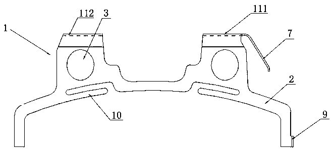
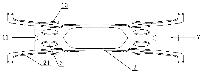
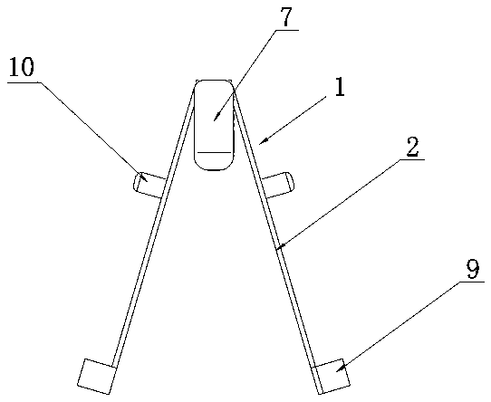
[0022] Such as figure 1 , figure 2 , image 3 and Figure 4 As shown, a disc brake leaf spring includes a leaf spring body 1, the leaf spring body 1 is composed of two fins 2, the upper part of the fins 2 is provided with a mounting hole 3, and the mounting hole 3 is used for The leaf spring body 1 is installed on the disc brake pump body 4, and the fixing pin 5 is used to pass through the installation hole 4 to fix it. The two fins 2 are connected as a whole through the connecting part 11 arranged at the top, and the side is an inverted V shape, the bottom of the wing 2 includes two feet 21, so that the lower part of the wing 2 is n-shaped, that is, a semi-enclosed frame structure, and the periphery of the braking surface of the brake pad 6 is provided with a step for the installation of the wing, which is assembled with the brake pad 6 At this time, the n-shaped frame structure of the wing 2 is installed on the step of the brake pad 6, so that the two feet 21 of the wing...


PUM


Abstract

The invention discloses a disc brake braking leaf spring. The disc brake braking leaf spring comprises a leaf spring body of an inverted V shape; the leaf spring body is formed by connecting two wing sheets, installation holes are formed in the upper parts of the wing sheets, and the two wing sheets are connected into a whole through connection parts arranged at the top end. The disc brake braking leaf spring is characterized in that a limiting strip used for abutting against the inner wall of a disc brake pump body is arranged at the top end of the leaf spring body, extends towards one side and is arranged towards the driving direction during working conditions. In the braking process, when brake pads are driven to move by a brake disc, the brake disc exerts force in the tangential direction of the disc and torque opposite to the rotation direction of the disc on the brake pads, and if fast inching braking is executed, the brake pads and fixing pins continuously collide with each other and generate the collision noise due to the connection gaps. By designing the limiting strip, the gaps between the braking pads and the fixing pins are eliminated in the braking process, the braking pads and the fixing pins are prevented from colliding with each other in the braking process, and therefore the braking process is more stable, and the noise generated by collision of the braking pads and the fixing pins can be lowered or eliminated.

Description

technical field [0001] The invention relates to the technical field of motorcycle accessories, in particular to a disc brake leaf spring. Background technique [0002] There will be a braking system on motorcycles, electric vehicles or bicycles, which is used to decelerate or stop the vehicle during driving, so the service braking system must have good stability. In the prior art, the brake system adopts disc brakes, including a disc brake pump body and two brake pads. The brake pads are installed on the disc brake pump body through fixing pins, and a plate for reset is provided between the two brake pads. Spring, leaf spring is also fixed by fixed pin. [0003] During the braking process, the two brake pads move relative to each other for braking. Since the tire has rotational inertia, the function of the brake pad is to clamp the brake disc of the tire to stop the tire from continuing to rotate. The force is mutual, so the brake disc of the tire is The brake pads have a ...

Claims


Application Information

Patent Timeline
Patent Type & Authority Patents(China)
IPC IPC(8): F16D65/097
CPCF16D65/097F16D65/0977
Inventor 虞小勇
Owner ZHEJIANG ZHANXIANG AUTOMOBILE & MOTORCYCLE PARTS
Learn More