Spin-orbit type reciprocating piston compressor

A reciprocating piston and compressor technology, applied in the field of compressors, can solve the problems of high temperature of the compressor, poor lubrication of the compressor, and degradation of lubrication performance, and achieve the goal of reducing friction noise, reducing temperature rise, and eliminating speed difference Effect

Active Publication Date: 2012-05-02
ZHEJIANG HONGYOU AIR COMPRESSOR MFG
View PDF5 Cites 0 Cited by
  • Summary
  • Abstract
  • Description
  • Claims
  • Application Information

AI Technical Summary

Problems solved by technology

However, it has been found through practice that the above-mentioned rotary-rail reciprocating piston compressor still has deficiencies, mainly manifested in relatively high operating noise and fast wear and tear of parts. Because its thrust pin or the bearing set on the thrust pin adopts the method that the cylindrical surface contacts and fits with the swirl surface of the swivel rail, as a result, the thrust pin or the bearing set on the thrust pin will be damaged due to the radius difference along the swirl surface. There is a speed difference between the outer surface and the orbital surface, that is, the outer end of the orbital surface has a larger contact rolling speed, while the inner end of the orbital surface has a smaller contact rolling speed due to the small radius, which inevitably makes The outer surface of the thrust pin or the bearing sleeved on the thrust pin and the surface of the rotary rail slip, which not only produces friction noise but also aggravates the wear of the parts at the fitting; 2) The compression heat generated by the compressor accumulates at t

Method used


Image

  • Spin-orbit type reciprocating piston compressor
  • Spin-orbit type reciprocating piston compressor
  • Spin-orbit type reciprocating piston compressor

Examples


Embodiment Construction

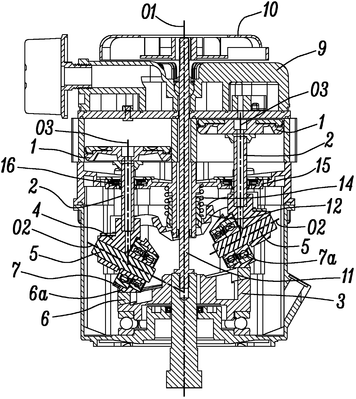
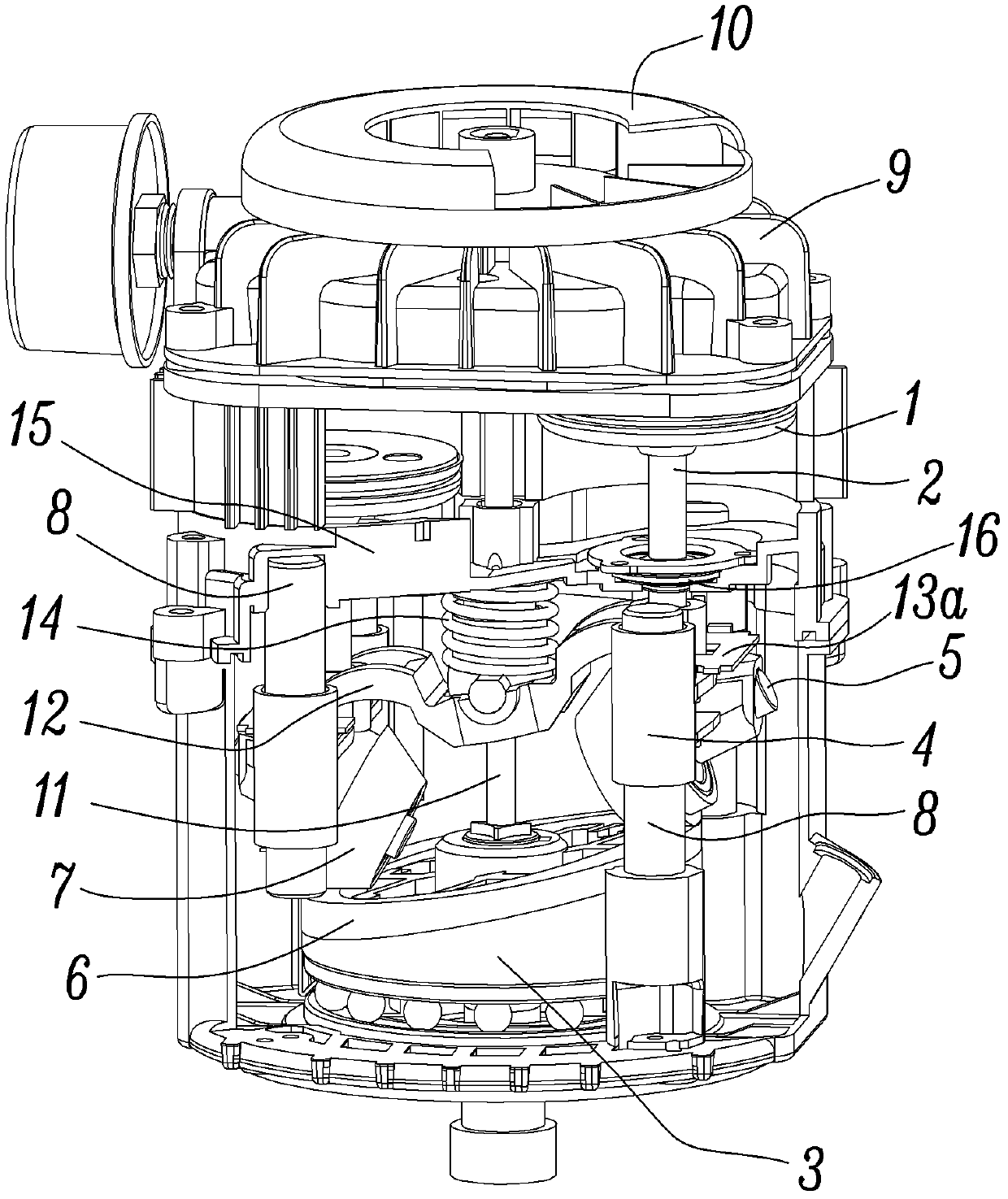
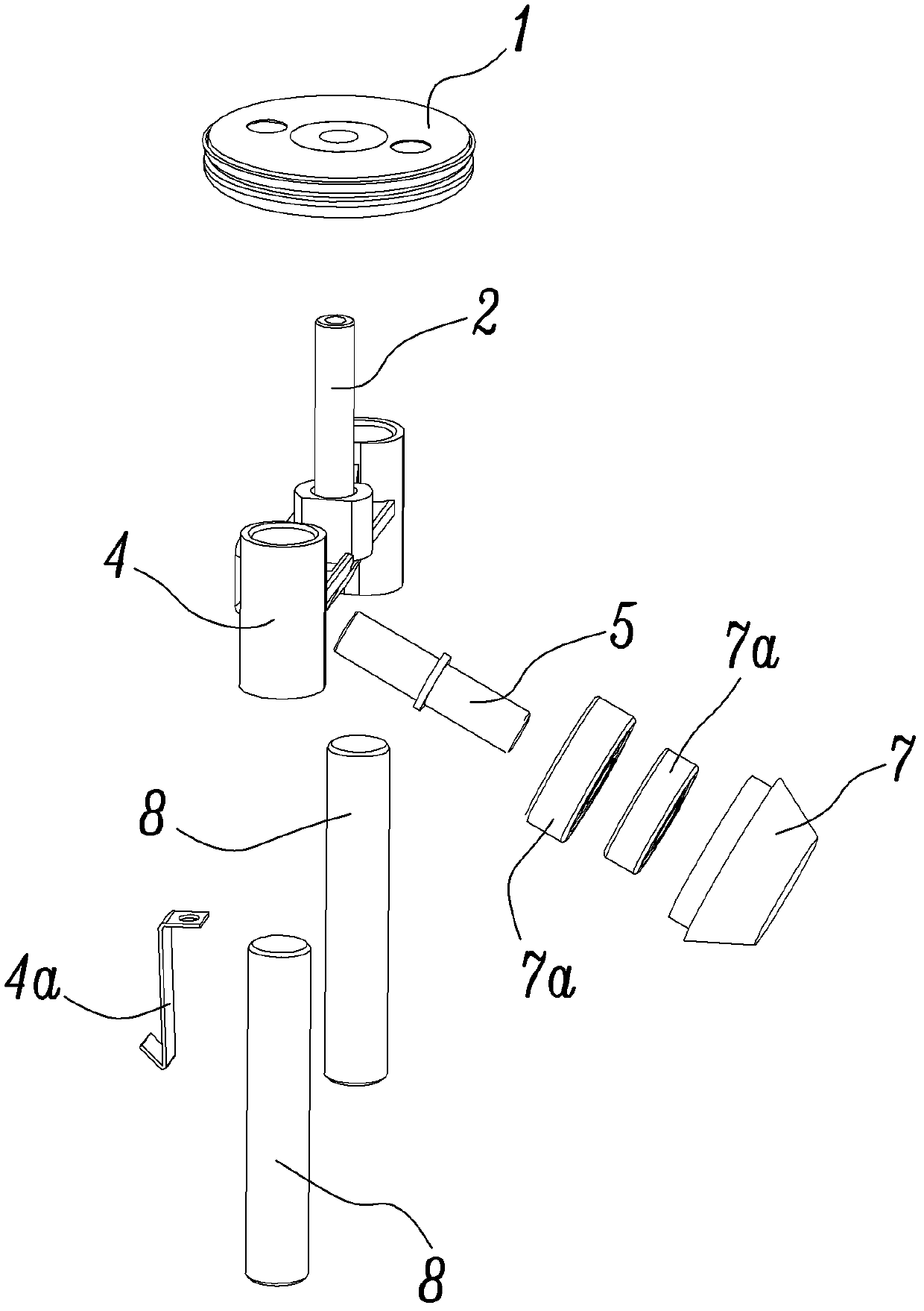
[0023] The present invention will be further described below with specific embodiment, see Figure 1-5 :

[0024] A rotary rail reciprocating piston compressor includes a piston 1, a connecting rod 2, a rotor 3, a slider 4 and a thrust pin 5. The rotor 3 is provided with a rotary rail 6, and one end of the thrust pin 5 is tightly connected to the slider 4. The other end of the thrust pin 5 is directly in contact with the swivel rail surface 6a of the swivel rail 6 (not shown in the figure), or indirectly with the swivel rail 6 through the rolling element 7 of the bearing structure. The rail surface 6a is contacted and kinematically matched; here the rolling body 7 can be directly rotated and set on the thrust pin 5 (not shown in the figure) or can be set on the thrust pin 5 through the bearing 7a (such as figure 1 and image 3 shown), when the structure of the sleeve bearing 7a is adopted, one bearing 7a can be equipped on each thrust pin 5, or two bearings 7a can be equippe...


PUM


Abstract

The invention relates to a spin-orbit type reciprocating piston compressor, belonging to the technical field of compressors. According to the spin-orbit type reciprocating piston compressor, a conical thrust pin or a rolling body is in contact and matched with a spin-orbit surface of a rotor, and therefore a speed difference at the contact part between the conical thrust pin or rolling body and the spin-orbit surface of the rotor can be reduced or even eliminated, and a slippage phenomenon between the thrust pin or rolling body and the spin-orbit surface of the rotor can be eased, thus reduction of part abrasion and frictional noise caused by slippage can be facilitated; because a cooling fan is used for directly cooling a cylinder cover of the compressor, whole unit temperature of the compressor can be reduced, temperature rise of lubricating oil is further reduced and lubricating performance of the lubricating oil is increased, and therefore reduction abrasion and frictional noise is facilitated as well; and because a release link mechanism is adopted and an interval eliminating spring is arranged on the release link at the same time, the release link can be well close to a sliding block under the action of the interval eliminating spring, and the sliding block enables the thrust pin or rolling body or the spin-orbit surface of the rotor to be well contact and matched, and therefore various intervals among parts are effectively eliminated, and reduction of impact noise and impact abrasion of parts can be facilitated.

Description

technical field [0001] The invention belongs to the technical field of compressors, and in particular relates to a reciprocating piston compressor, and more specifically relates to a compressor which utilizes a rotary rail to generate reciprocating motion of a piston. Background technique [0002] Chinese patent application CN101644246 discloses a reciprocating piston compressor with a rotary rail structure, which includes a rotor, a sliding seat, several sliders and several thrust pins, the rotor is provided with a rotary rail, and the There are several sliding rails parallel to the axis of the rotor on the sliding seat. The sliding block slides or rolls with the sliding rail. One end of the thrust pin is connected with the sliding block and moves along the sliding rail together with it. The thrust pin The other end directly or through the bearing is matched with the rotary rail and is driven by the rotary rail to relatively move along the working surface of the rotary rail...

Claims


Application Information

Patent Timeline
IPC IPC(8): F04B27/12
Inventor 耿爱农陈君立阮勤江
Owner ZHEJIANG HONGYOU AIR COMPRESSOR MFG
Why Eureka
Try Eureka