“Brake-by-wire” type brake system

a technology of brakes and wires, applied in the direction of brake systems, brake components, transportation and packaging, etc., can solve the problems of high cost of known systems, high number of components, and failure to meet the requirements of braking, so as to achieve simple and space-saving design, more cost-effective

Active Publication Date: 2015-07-14
CONTINENTAL TEVES AG & CO OHG
View PDF33 Cites 14 Cited by
  • Summary
  • Abstract
  • Description
  • Claims
  • Application Information

AI Technical Summary

Benefits of technology

[0011]It is therefore an object of at least one embodiment of the present invention to provide a “brake-by-wire” type brake system which is more cost-effective, and has a simpler and more space-saving design.
[0012]There is provision here that a force / travel characteristic of the pedal travel simulator is provided in a controllable fashion. Controlling the pedal characteristic permits an additional travel with a limited force level to be enabled if the “brake-by-wire” system fails or a higher braking performance is necessary, with the result that the pedal travel simulator no longer has to be deactivated in the fallback level. It is therefore advantageous that there is no longer any need for a device for deactivating or activating the pedal travel simulator, and as a result of which the monitoring thereof is eliminated.
[0013]The control of the force / travel characteristic of the pedal travel simulator can preferably be provided in a force-dependent fashion, with the result that, starting from a predetermined foot force applied to the brake pedal, prolongation of the pedal travel is made possible and the reaction force which occurs in the process does not exceed a defined limiting value. Alternatively, the control of the force / travel characteristic of the pedal travel simulator, and therefore also of the pedal characteristic, could also be provided in a travel-dependent fashion.

Problems solved by technology

In the event of failure of the vehicle electronics or failure of the on-board power system, the check valve 14 cannot be switched over, with the result that the braking occurs in the fallback level.
It is considered disadvantageous in the previously known brake system that the function of the electro-hydraulic device has to be monitored.
In addition, the known system is costly and has a high number of components.

Method used


Image

  • “Brake-by-wire” type brake system
  • “Brake-by-wire” type brake system
  • “Brake-by-wire” type brake system

Examples


Embodiment Construction

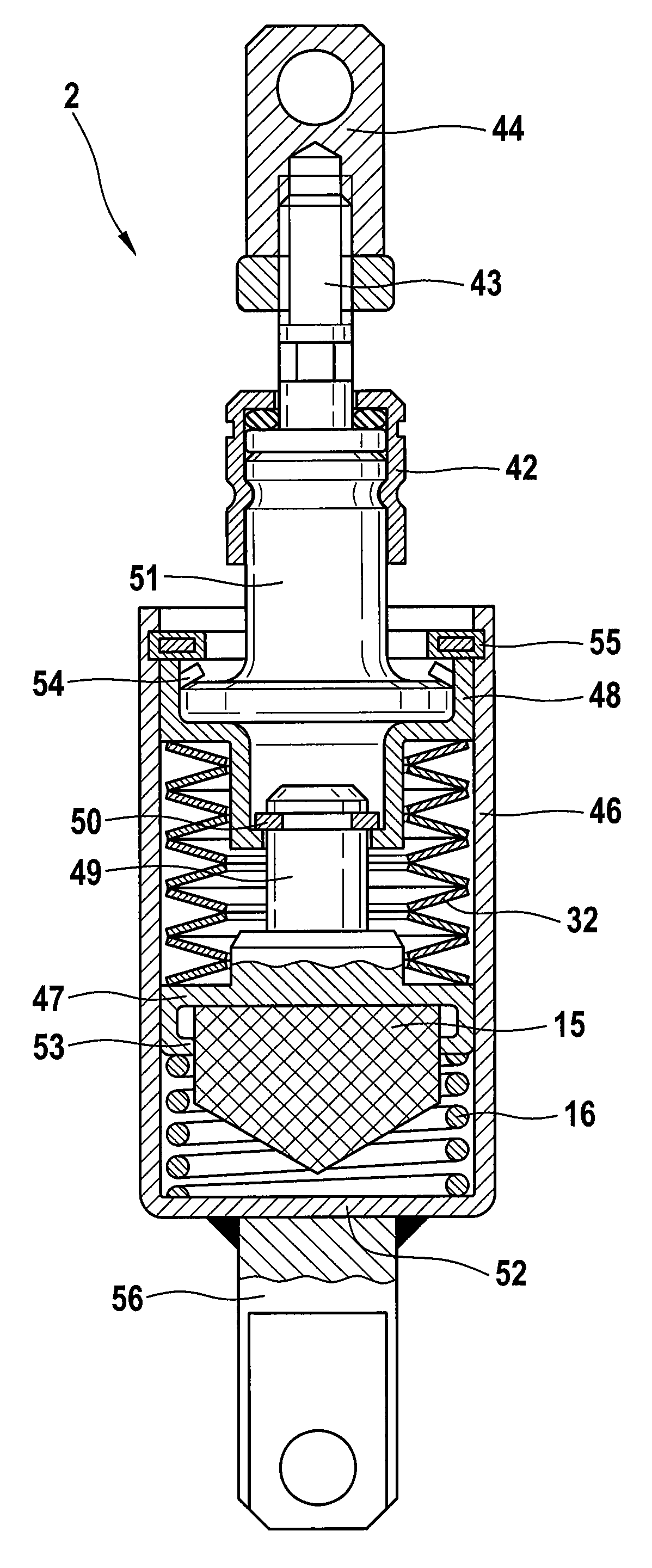
[0047]In order to present a simpler and more cost-effective “brake-by-wire” type brake system, according to the exemplary embodiments described below there is provision that a force / travel characteristic of the pedal travel simulator 2, which is formed by at least one simulator element 15, is provided in a controllable fashion. Controlling the pedal characteristic allows additional travel with a limited force level to be enabled if the “brake-by-wire” system fails or a higher braking performance is necessary, with the result that separate deactivation of the pedal travel simulator in the fallback level no longer has to take place outside the “brake-by-wire” operating mode according to the described prior art. It is therefore particularly advantageous that there is no longer any need for a device for deactivating or activating the pedal travel simulator, as a result of which monitoring thereof can also be dispensed with.

[0048]The force / travel characteristic, i.e. the pedal travel, is...


PUM


Abstract

A “brake-by-wire” type brake system for a motor vehicle, having a brake pressure sensor which can be activated by a brake pedal of a pedal unit and can be connected to wheel brakes of the vehicle outside the “brake-by-wire” operating mode, having a pressure source which can be actuated by an electronic control unit and can be connected to the wheel brakes of the vehicle in the “brake-by-wire” operating mode, and having a pedal travel simulator which interacts with the brake pedal and is formed by at least one simulator element, and a restoring force which acts on the brake pedal independently of the actuation of the pressure source can be simulated in the “brake-by-wire” operating mode. In order to provide a simpler and more cost-effective “brake-by-wire” type brake system, a force / travel characteristic of the pedal travel simulator is provided in a controllable fashion.

Description

CROSS REFERENCE TO RELATED APPLICATION[0001]This application is the U.S. National Phase Application of PCT International Application No. PCT / EP2010 / 050368, filed Jan. 14, 2010, which claims priority to German Patent Application No. 10 2009 000 235.9, filed Jan. 15, 2009, and German Patent Application No. 10 2009 002 885.4, filed May 7, 2009, the contents of such applications being incorporated by reference herein.FIELD OF THE INVENTION[0002]A “brake-by-wire” type brake system for a motor vehicle, having a brake pressure generator which can be activated by means of a brake pedal of a pedal unit and can be connected to wheel brakes of the vehicle outside the “brake-by-wire” operating mode, having a pressure source which can be actuated by means of an electronic control unit and can be connected to the wheel brakes of the vehicle in the “brake-by-wire” operating mode, having means for detecting a driver's deceleration request, and having a pedal travel simulator which interacts with th...

Claims


Application Information

Patent Timeline
Patent Type & Authority Patents(United States)
IPC IPC(8): B60T13/74B60T7/04B60T8/40B60T13/573B60T13/66
CPCB60T7/042B60T8/409B60T8/4077B60T13/573B60T13/662B60T13/745
Inventor SELLINGER, THOMASDROTT, PETERKRÄMER, HORST
Owner CONTINENTAL TEVES AG & CO OHG
Why Eureka
Try Eureka