

"brake-by-wire" type brake system
- Summary
- Abstract
- Description
- Claims
- Application Information
AI Technical Summary
Benefits of technology
Problems solved by technology
Method used
Image

Examples
Embodiment Construction
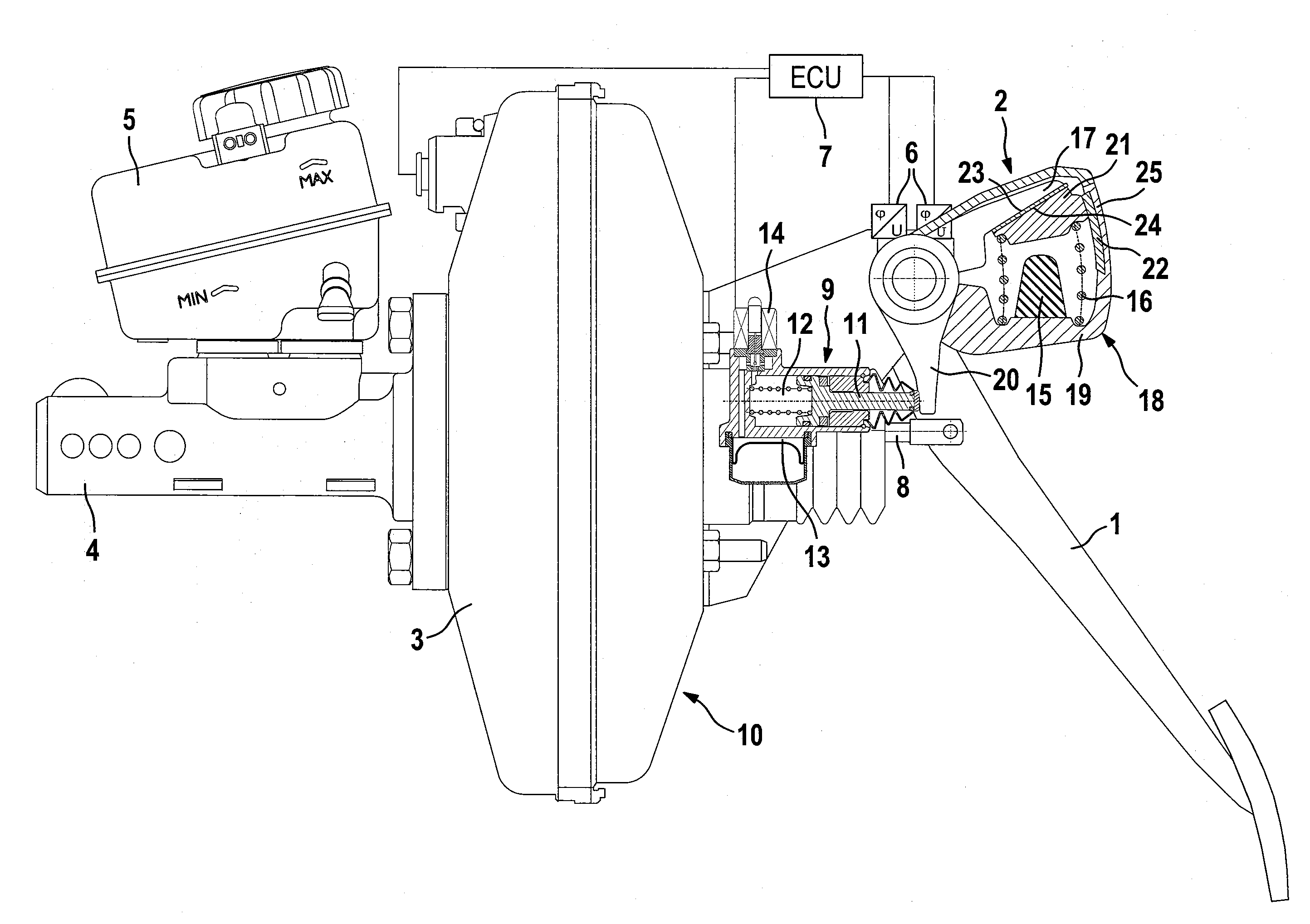
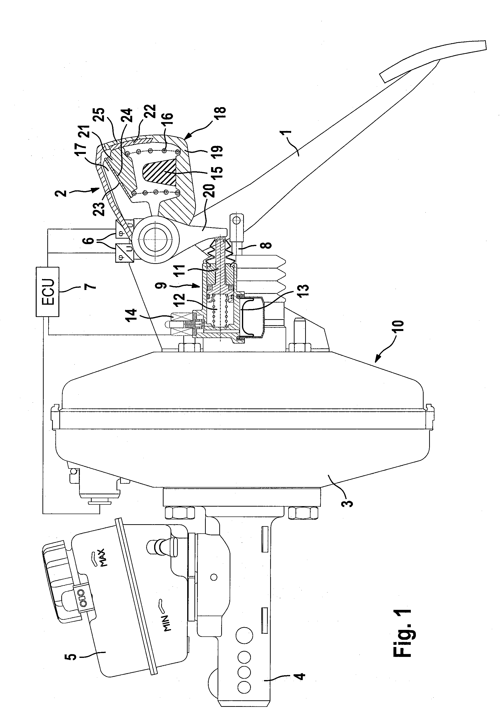
[0040]The “brake-by-wire” type brake system for a motor vehicle, illustrated in FIG. 1, is known from the prior art and is composed essentially of a brake activation unit 10, a brake pedal 10, a pedal travel simulator 2, an electronic control unit 7, which is illustrated only schematically, and wheel brakes (not shown) which are connected to the brake activation unit 10 with the optional intermediate connection of a hydraulic open-loop or closed-loop control unit. The brake activation unit 10 is formed by a brake booster, preferably an underpressure brake booster 3, a master brake cylinder, for example a tandem master cylinder 4, which is connected downstream of the brake booster 3 and to whose pressure spaces (not illustrated) the abovementioned wheel brakes of the motor vehicle are connected, as well as a pressure medium reservoir vessel 5 which is assigned to the master brake cylinder 4. The brake pedal 1, which serves for the activation of the brake booster 3 by the driver, inte...
PUM
 Abstract
Description
Claims
Application Information