Our nation faces a multi-trillion dollar problem in deteriorated infrastructure.
The submerged or subterranean portion of many if not most decades-old distribution pipelines, a portion often out of
sight and out of mind, is at great risk and in dire need of maintenance, especially cleaning.
When designated for
periodic maintenance, infrastructure remediation is often postponed due to lack of budget in the face of the inefficiencies and high costs of available, prior art solutions.
Such postponement only further complicates the
maintenance problem and increases costs when the problem is eventually addressed.
Furthermore, the
engineering of the original designs and structures tends to become degraded as living organisms encounter and
exploit these created ecological niches, for example, as Zebra Mussels adhere to and grow within conduits.
Such ‘marine
fouling’ has become a significant and costly problem, and serves as a prime example of both the operation of evolution and of unintended and unsuspected consequences.
These systems incorporate submerged intake and
discharge conduits, highly susceptible to
fouling, and raise environmental concerns.
Over and above the reduction of volume, the
rough surface of
fouling creates friction, causing internal turbulence and effectively compounding the restriction of flow rates.
Unfortunately, achieving higher flow rates via increased pumping pressure requires an exponential increase in pumping
horsepower, and in the associated costs.
The extra pumping pressure then also puts greater strain and wear on the infrastructure, decreasing its safety and operative life.
Using pumping pressure to increase flow rates has a negative environmental
impact as well.
As flow rates increase,
plankton, fish or even marine mammals are more likely to become sucked into these conduits and die.
However, removal of marine fouling is a complex problem.
New regulatory compliance requirements for debris disposal also
impact these adjustments.
An individual chunk of dislodged debris, falling to the floor (i.e., the “invert”) of the conduit, may encompass several cubic feet, weigh hundreds of pounds, and create a very significant work process obstacle.
It also may
pose a significant safety
hazard to a human diver in an enclosed environment, particularly if
visibility is poor, as it tends to be when water is turbid and lighting is both restricted and limited.
No prior art device eliminates the need for manual procedures performed by divers and surface crews without significant disadvantages and limitations (either to address intended functionality or to provide a complete solution).
This failure prevents industry or government from remediating infrastructure in any meaningful way.
Divers obviously are not automated apparatus and, at best, use diver-operated tools.
More importantly, divers always must put their lives ‘at risk’ in hazardous environments and in particular, the penetrating into long conduits where there is no direct access to the surface.
The further removed, and the more different, the environment is from that experienced by the operator, the more likely it will be that interpretation will introduce errors.
Furthermore, semi-automated methods still require divers to overcome limitations of the mechanical apparatus (e.g., tasks the apparatus cannot perform) or to correct failures in its automated control apparatus.
The more removed the operator is from both the apparatus and the environment, the more limited the operator's knowledge of the actual conditions—of the environment and of the apparatus—will be; and the more likely it becomes that an unanticipated and un-sensed
divergence from the presumed condition will give rise to a problem or even a disaster.
Fully automated methods do not require either an operator's or a diver's immediate and continual attention and continued involvement, but are limited in the types of tasks or environments in which they can perform.
For example, the prior art may disclose an apparatus with the ability to perform some level of inspection in an automated fashion, but the same apparatus cannot perform remediation.
Alternatively, the prior art may disclose an apparatus with the ability to remediate a round, small
diameter conduit, but unable to negotiate obstacles.
In all
fully automated examples (i.e., autonomous) of prior art apparatus for submerged infrastructure remediation, (e.g. power
plant cooling systems), divers must be used to compensate for numerous limitations, a serious, hazardous, and costly
disadvantage.
Unfortunately, as infrastructure ages it becomes more fragile and de-watering case histories, chronicling significant structural damage and even collapse, have made de-watering a practice of last resort.
Furthermore, the nature of the submerged infrastructure or the material in which it is submerged may make de-watering impractical or even impossible.
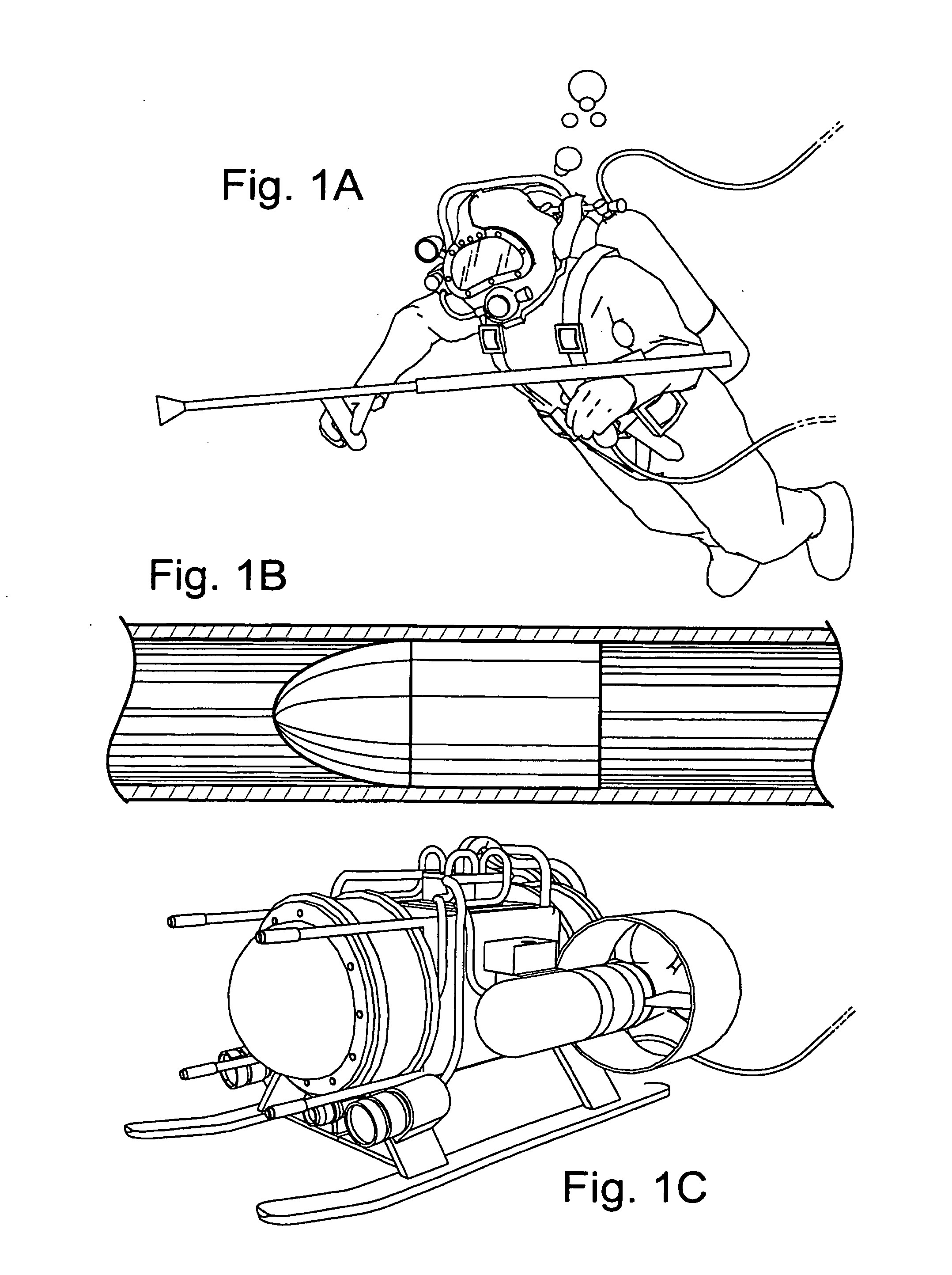
The manual method of using of divers (FIG. 1A) is the lowest
common denominator, and least efficient means to meet INSOP functionality.
It has significant disadvantages and limitations.
Navigation is a further limited by available air supply, tethers, support divers, and safety requirements.
Divers are limited to work processes that can be performed using hand-held or handcontrollable implements, and work optimization is limited by human
perception,
motor control, and responses.
Given the limitations of the divers as explained above, positioning errors result in unacceptable abrasion to the work surface by the more powerful
cutting action.
Limitations include the lack of means to exactly position this
nozzle to the work surface, control the amount of abrasion, and to control uniformity.
A limitation of this apparatus was the inability to
cut more than a “swath” of a few feet wide in any
single pass, requiring multiple passes.
Other limitations included the lack of navigation aids to maintain a straight
cutting swath, blinding of the diver caused by the
turbidity of
machine operation, and no means to prevent the deadly potential of crushing or drowning of the diver by entanglement should power to the
machine be lost and it free falls from the work surface.
A general limitation of this method is that all semi-automated approaches still must incorporate diver-operation and divers to overcome limited functionality.
One limitation of these devices is they impede operational flow in requiring a bulkhead to be placed over the conduit mouth to complete the seal with the conduit.
Disadvantages and limitations of pigs are numerous.
Without the ability to remove accumulated debris or to optimize work processes in response to conditions, accumulation builds in the path of the pig until such time as it becomes stuck.
This further creates a navigation problem, as the pig, unable to avoid an obstacle, merely crashes into it.
Pigs are not a scalable solution: A different size of pig is required for each size of conduit
diameter.
As diameters increase, the pig becomes disproportionately less effective.
Further disadvantages that
impact performance include a lack of means to insert itself into a conduit, supply its own
hydraulic pressure, completely clean a conduit in a
single pass, free itself when stuck, or to recover the debris that it has dislodged.
This multi-
ton projectile, the largest pig of its time, was eventually abandoned for its inability to adequately clean a mere twelve-foot conduit as well as for its tendency to get stuck in the conduit.
One limitation of this prior art is the requirement of flowing water to rotate fan blades as a (ineffective) source of power.
Another limitation is the use of rotating mechanical scrapers without means to prevent their jamming up when encountering a large clump of debris and causing the device to become stuck.
In addition to requiring a tow cable, other limitations include the requirement of means to divide
towing power between moving the apparatus forward, and rotating its scrapers.
This division increases the risk of the apparatus getting stuck or breaking the tow cable.
One limitation is the need to supply hydraulic power through a long hose from the surface down to the rotating the scraper motor.
Line loss through the hose results in significant power drop.
These limitations represent considerable complexity in apparatus, yet do not provide other than passive means to detect and overcome even minimal surface variations, let alone large obstacles.
Furthermore, compound rotation doubles hydraulic power requirements.
A
disadvantage of this approach was the “kickback” of the jets, buffeting the sled, and causing the sled runner to get stuck at the joints between sections of conduit.
This required yet more motors, increasing power requirements and
line loss.
The above prior art, consisting of both non-intelligent and semi-automated methods, beyond the various individual limitations and disadvantages, fail to address INSOP requirements.
This failure manifests in an over dependence upon manual methods, such as divers below and large support crews above the surface.
With over dependency on manual methods and human participation, these examples of the prior art become economically infeasible.
The study concludes that the ROV has usefulness for inspection and navigation purposes, but has significant limitations in the inability to perform any maintenance or repair.
One cause has been that prior art ROV design has required adapting third-party attachments (such as manipulators) to the body of the ROV as a means to accomplish any work process, and a lack of
modularity (e.g., an ROV is either a swimming vehicle or a tracked vehicle, but can not do both).
The tracked vehicle was restricted to operation on flat and level surfaces.
An operator, faced with poor
visibility, would fail to locate the
mussel colonies or even drive the ROV off course and roll it over.
The apparatus further lacked automated means to manage the debris hose after it reached the surface so that debris removal and disposal rates could not be continuously coordinated.
Despite its promise over prior art, the MIST (and any similar prior art) still suffered significant limitations and disadvantages: Inspection was limited a operator / diver requirement.
Navigation was limited by a fixed, non-articulating frame.
Scalability was limited by a fixed and non-expandable configuration.
Optimization was limited by conflicting requirements: a diver and deadly high-
voltage current in close proximity.
Performance was limited by reliance on manual inspection, navigation and optimization, and an inadequate debris
recovery system.
Fully automated methods do not require diver involvement but are limited in the types of tasks or environments in which they can perform.
For example, the prior art may disclose an apparatus with the ability to perform some level of inspection in an automated fashion, but the same apparatus cannot perform remediation.
This limitation is caused by automated apparatus architecture that is of a monolithic nature and lacking standardized or
interchangeable parts.
Alternatively, the prior art may disclose an apparatus with the ability to remediate a round, small
diameter submerged conduit, but is unable to negotiate obstacles.
Despite various advances applied to inspection and navigation problems, automated ROVs suffer the same limitations and disadvantages of Manually operated ROVs.
Control systems for
fully automated apparatus, including various types of autonomous or robotic vehicles, are well known in the prior art, but have seen only limited application to systems for infrastructure remediation.
The patent fails to disclose how the mechanical aspect of the interface is accomplished beyond including a “power take-off’, flexibility, and quick connect capability, and does not teach any method for integrating power and communication
interconnection into a single
bus.
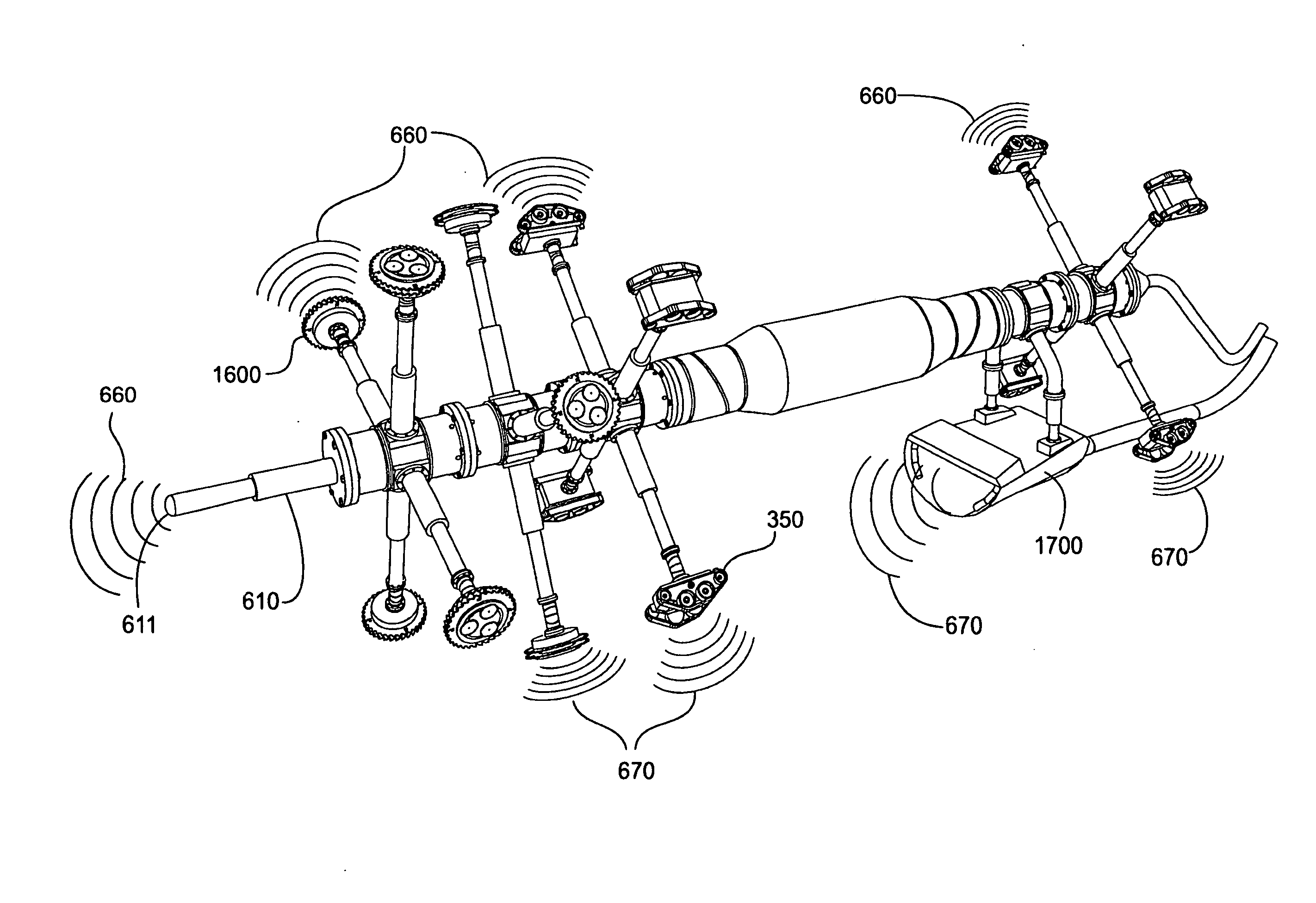
Although multiple tool heads attached to one
robot are disclosed, no means of coordinating the activities of those tool heads is disclosed.
All prior art apparatus and methods for infrastructure remediation, including but not limited to those discussed above, fail to address one or more of the INSOP infrastructure remediation solution requirements, and therefore fail to achieve the advantages and
synergy of meeting all of those requirements.

