
Pipe alignment device

a technology of pipe alignment and jig, which is applied in the direction of active open surveying means, surveying instruments, instruments, etc., can solve the problems of distal end of an existing pipe, tool is not for use with the distal end, and the level cannot attach itself onto the distal end of a pip

Inactive Publication Date: 2015-07-14
MCCARTHY SHERWIN W
View PDF15 Cites 14 Cited by
  • Summary
  • Abstract
  • Description
  • Claims
  • Application Information

AI Technical Summary

Benefits of technology

The invention is an adaptor coupling that can be attached to the end of an existing pipe to securely connect to a device. It also allows for easy attachment of an alignment housing to the invention. This makes it easier to attach the invention to existing pipes and reduces the need for additional connections.

Problems solved by technology

However, the level is unable to attach itself onto a distal end of a pipe, and project a leveled laser there from.
However, the hand tool is unable to attach onto an open, distal end of an existing pipe in order to project a leveled laser line there from.
Again, the tool is not for use with the distal open end of an existing pipe.
Again, the tool is unable to secure itself onto the open distal end of a pipe for use in aligning a leveled laser line therefrom, and in use with pipe fitting.

Method used


Image

  • Pipe alignment device
  • Pipe alignment device
  • Pipe alignment device

Examples


Embodiment Construction

[0033]The following detailed description is merely exemplary in nature and is not intended to limit the described embodiments of the application and uses of the described embodiments. As used herein, the word “exemplary” or “illustrative” means “serving as an example, instance, or illustration.” Any implementation described herein as “exemplary” or “illustrative” is not necessarily to be construed as preferred or advantageous over other implementations. All of the implementations described below are exemplary implementations provided to enable persons skilled in the art to practice the disclosure and are not intended to limit the scope of the appended claims. Furthermore, there is no intention to be bound by any expressed or implied theory presented in the preceding technical field, background, brief summary or the following detailed description.

[0034]Detailed reference will now be made to the preferred embodiment of the present invention, examples of which are illustrated in FIGS. ...


PUM


Abstract

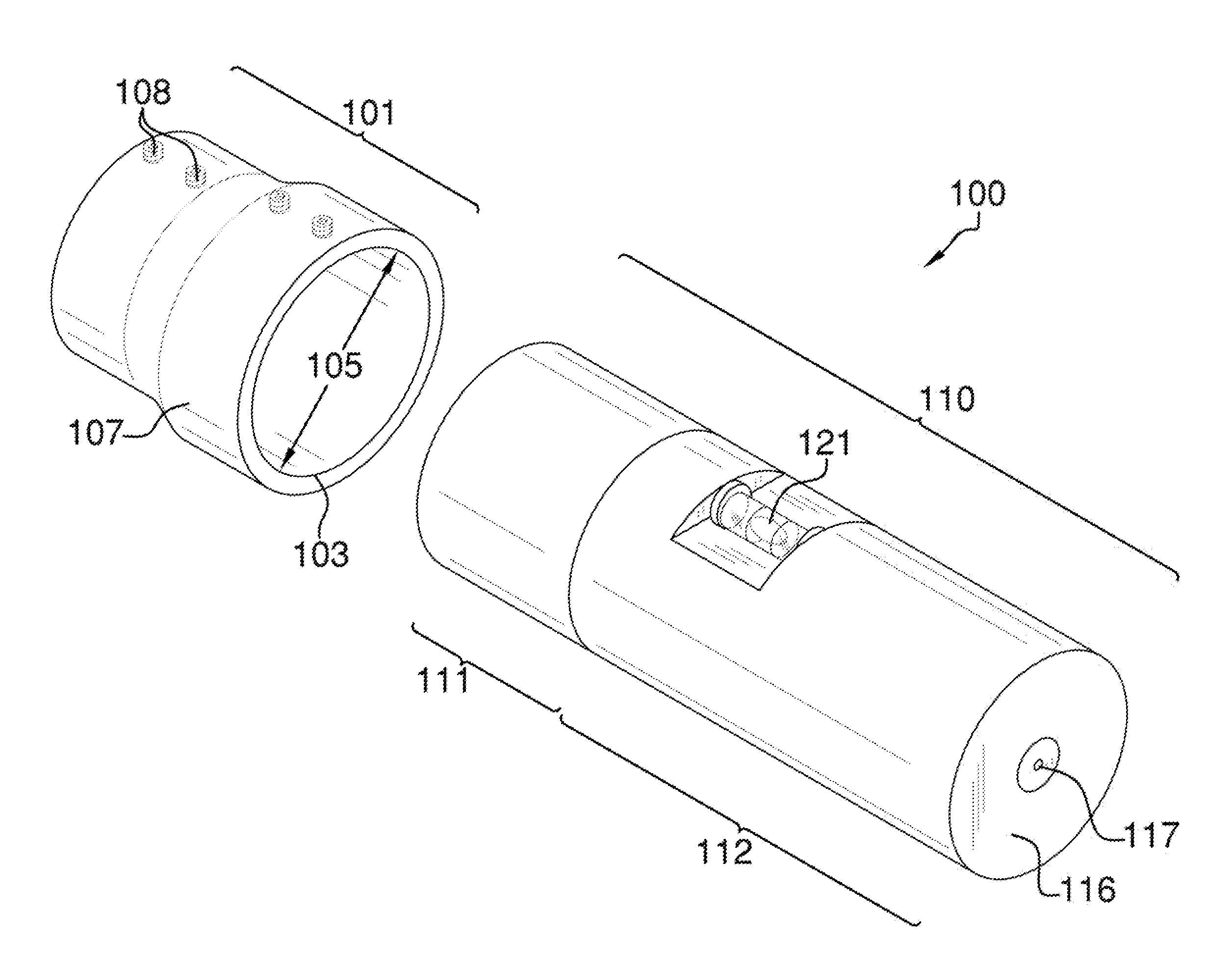
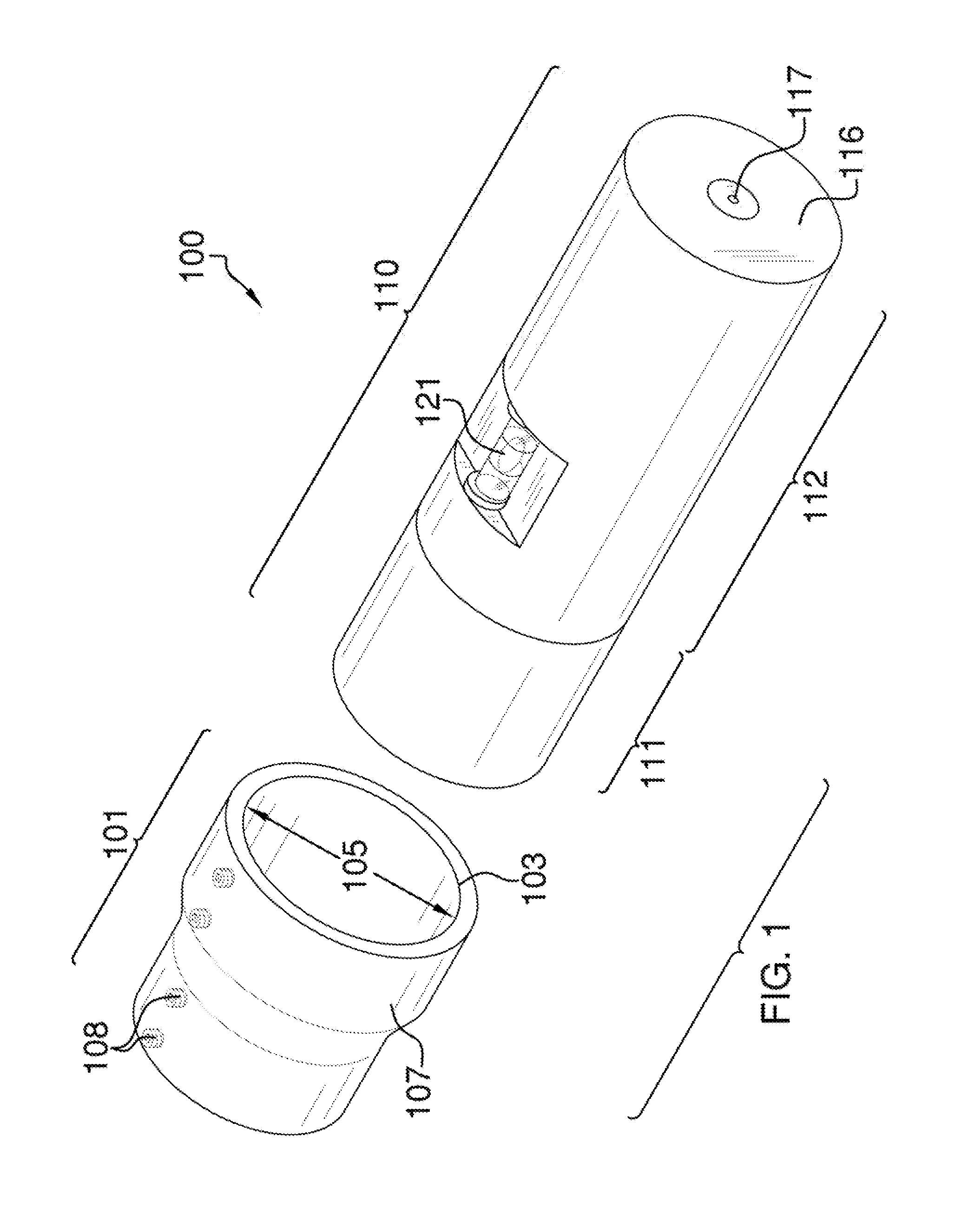
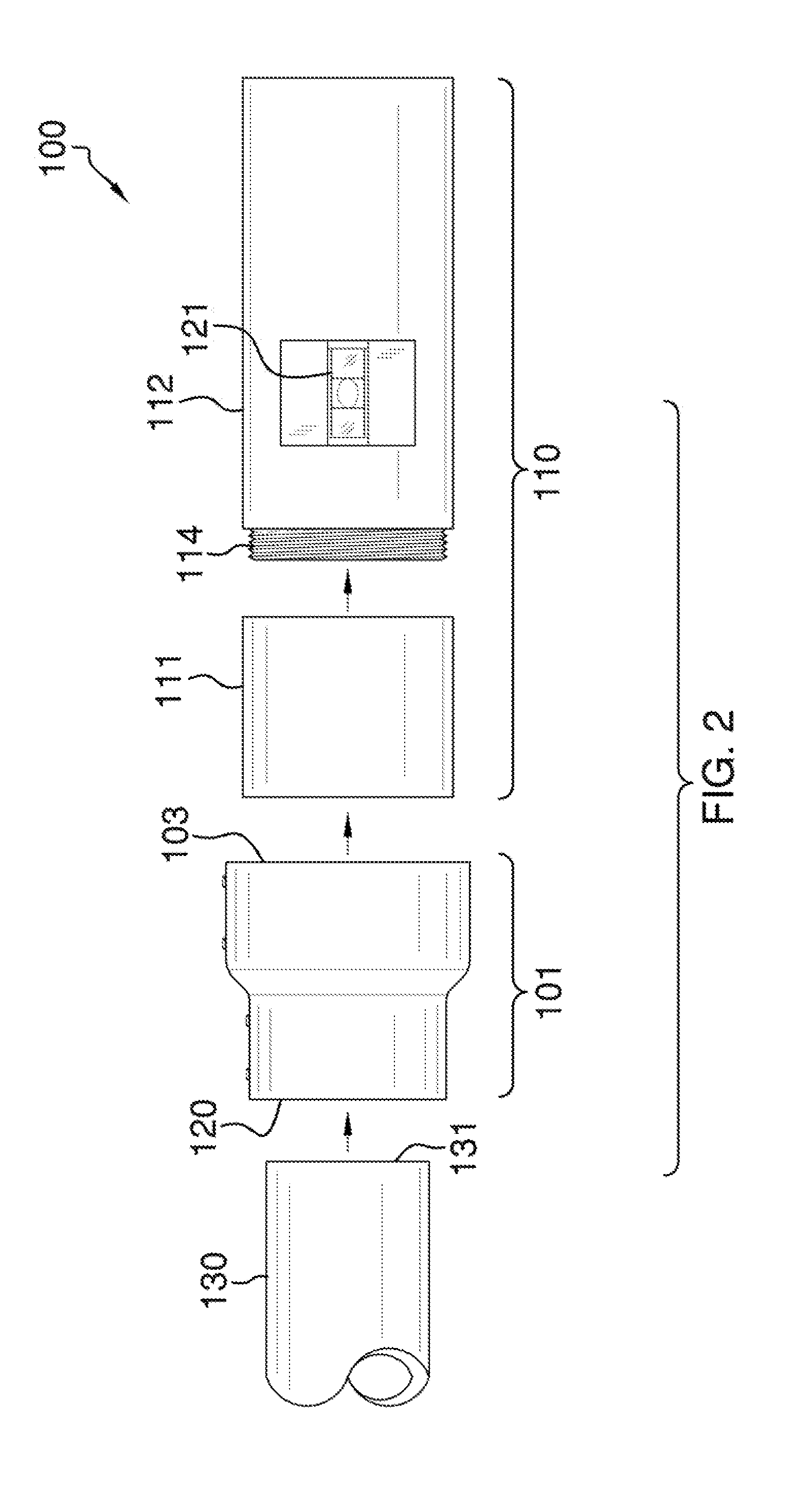
The pipe alignment device is a device adapted for use with an existing pipe in order to project a laser line from a distal end of the existing pipe. The pipe alignment device includes an adaptor coupling that enables a leveling laser and spirit level to attach to the distal end of the existing pipe in order to determine a level alignment of the leveling laser. The leveling laser and the spirit level are mounted on an alignment housing that is able to attach onto the adaptor coupling. The adaptor coupling includes a plurality of set screws that secure the adaptor coupling to the distal end of the existing pipe as well as to secure the alignment housing to the adaptor coupling.

Description

CROSS REFERENCES TO RELATED APPLICATIONS[0001]Not ApplicableSTATEMENT REGARDING FEDERALLY SPONSORED RESEARCH[0002]Not ApplicableREFERENCE TO APPENDIX[0003]Not ApplicableBACKGROUND OF THE INVENTION[0004]A. Field of the Invention[0005]The present invention relates to the field of pipe aligning jigs, more specifically, an alignment device that is able to attach onto an open end of a pipe.[0006]Pipe fitting is a difficult skill to master. This is especially true where open ends of a pipe are difficult to reach, and require assistance in determining a level point in space therefrom. What is needed is a device that aids a pipe fitter in ascertaining a leveled point in space, which is projected from the distal end of the existing pipe. The device of the present application addresses this need by providing an alignment device that is adapted or configured for use with the distal end of the existing pipe.[0007]B. Discussion of the Prior Art[0008]As will be discussed immediately below, no pri...

Claims


Application Information

Patent Timeline
Patent Type & Authority Patents(United States)
IPC IPC(8): G01C15/00G01B11/27
CPCG01B11/27G01C15/004G01B11/272G01C9/28
Inventor MCCARTHY, SHERWIN W.
Owner MCCARTHY SHERWIN W
Learn More