Eureka AIR delivers breakthrough ideas for toughest innovation challenges, trusted by R&D personnel around the world.

Computer-implemented composite simulation method and non-transitory computer medium for use in molding process

Active Publication Date: 2015-07-14
CORETECH SYST
View PDF4 Cites 3 Cited by
  • Summary
  • Abstract
  • Description
  • Claims
  • Application Information

AI Technical Summary

Benefits of technology

The present patent provides a method for analyzing the flow of material in a running system used in manufacturing processes. The method assumes that the flow of material is steady and reduces the time needed for simulation. This simplifies the modeling of the process and allows for faster computing times compared to conventional methods.

Problems solved by technology

In general, the setting of molding conditions in an injection molding machine requires a large number of trial molding operations and a long setting time because the setting work greatly depends on the know-how and experience of an operator of the injection molding machine, and various physical values affect one another as well.

Method used


Image

  • Computer-implemented composite simulation method and non-transitory computer medium for use in molding process
  • Computer-implemented composite simulation method and non-transitory computer medium for use in molding process
  • Computer-implemented composite simulation method and non-transitory computer medium for use in molding process

Examples


Embodiment Construction

[0023]The following description of the disclosure accompanies drawings, which are incorporated in and constitute a part of this specification, and illustrate embodiments of the disclosure, but the disclosure is not limited to the embodiments. In addition, the following embodiments can be properly integrated to complete another embodiment.

[0024]References to “some embodiments,”“an embodiment,”“exemplary embodiment,”“other embodiments,”“another embodiment,” etc. indicate that the embodiment(s) of the disclosure so described may include a particular feature, structure, or characteristic, but not every embodiment necessarily includes the particular feature, structure, or characteristic. Further, repeated use of the phrase “in the embodiment” does not necessarily refer to the same embodiment, although it may.

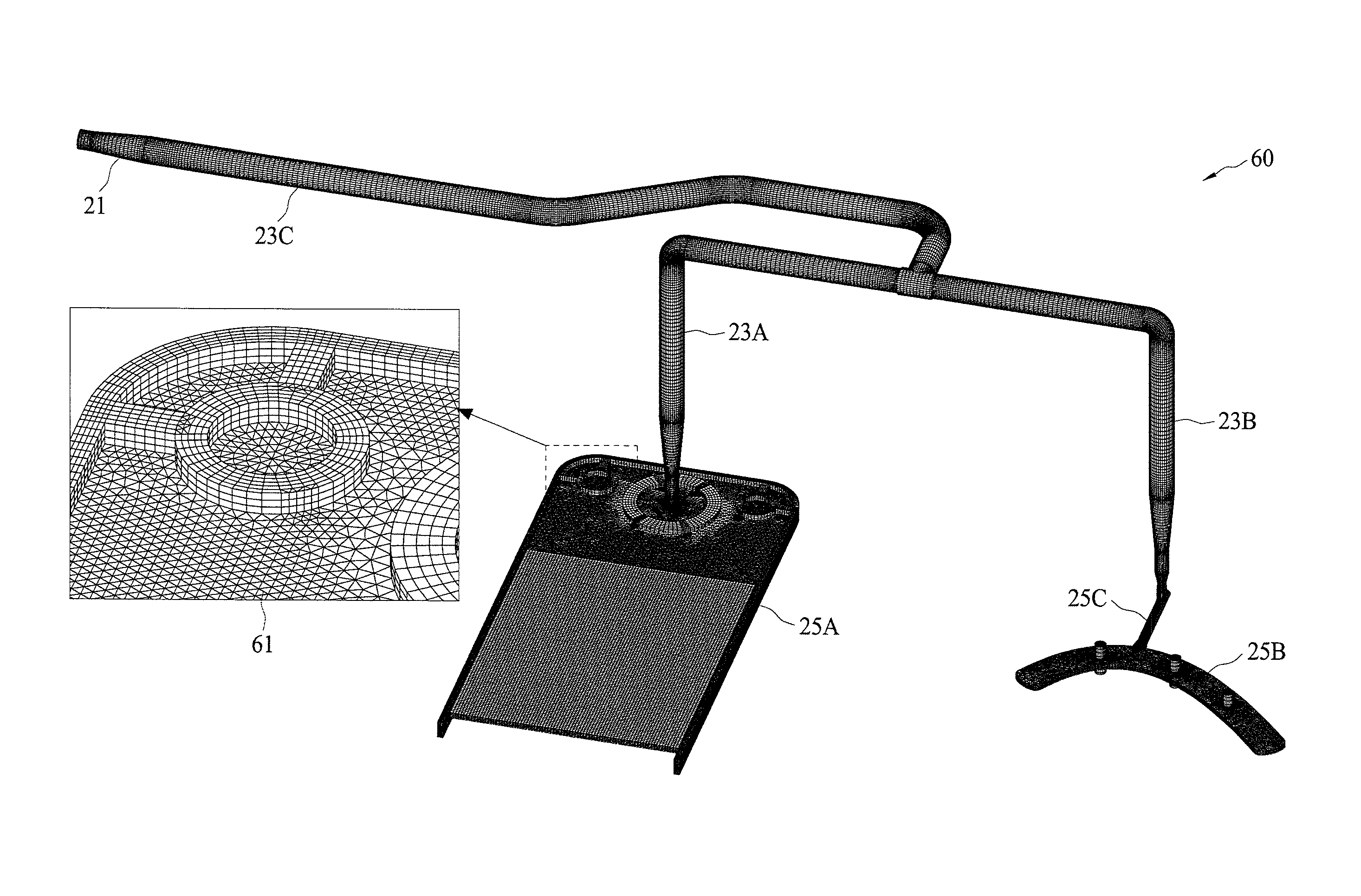
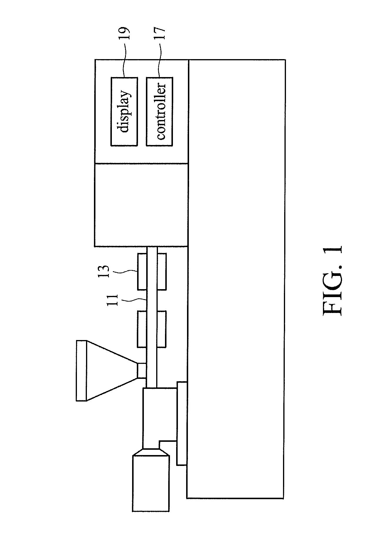
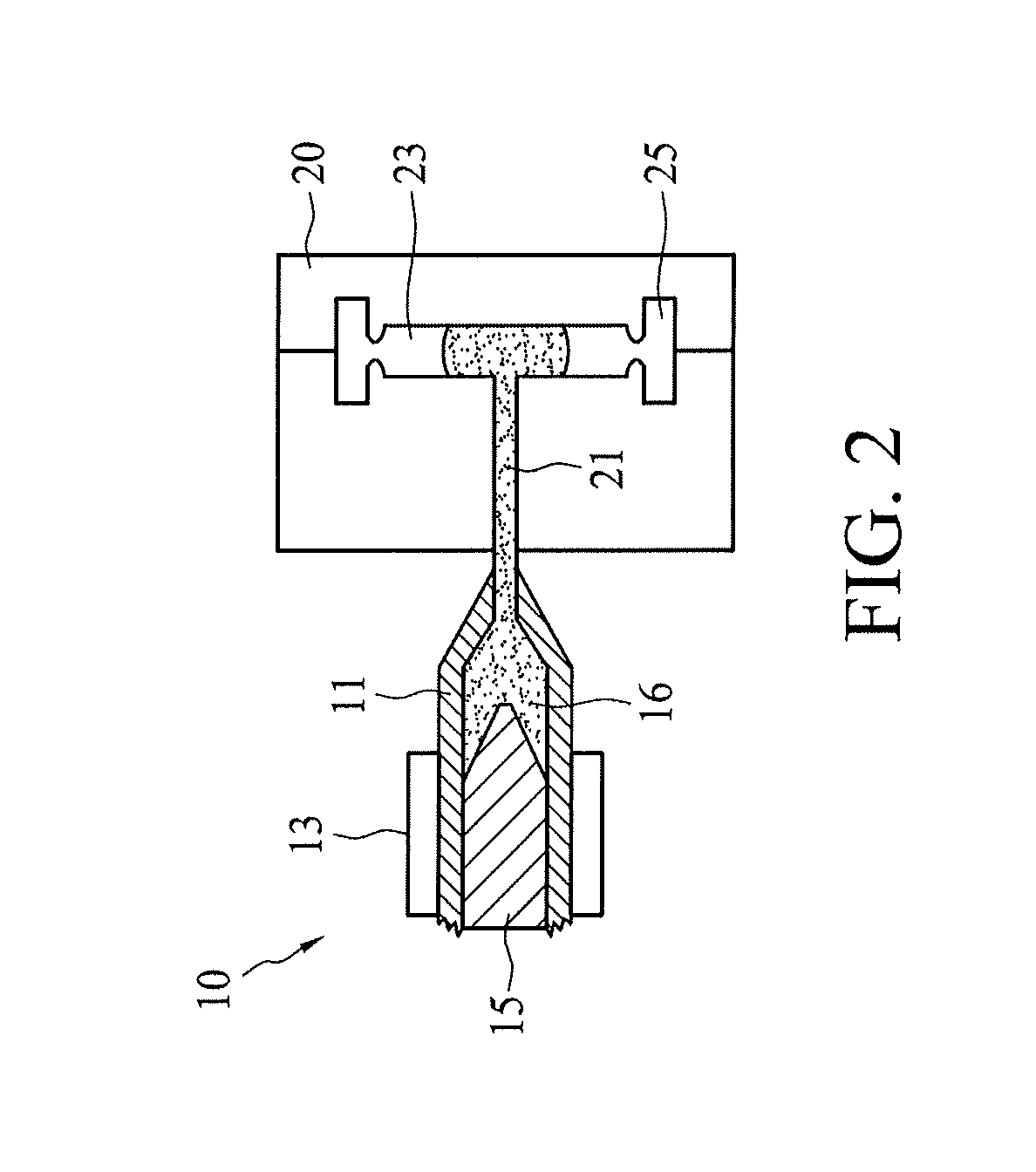
[0025]The present disclosure is directed to a computer-implemented composite simulation method and a non-transitory computer medium for use in a molding process by a computer process...


PUM


Abstract

A computer-implemented method for use in a molding process by a computer processor includes specifying a simulating domain having a cavity part and a runner part; setting a filling condition of the cavity part without taking into consideration the runner part, wherein the filling condition includes gate pressures and filling rates of the cavities of the cavity part; and performing a steady state analysis to calculate flow conditions of a plurality of runner designs for the runner part by taking into consideration the filling condition of the cavity part, wherein the flow conditions include flow rates of a molding material in the runners of the runner part.

Description

TECHNICAL FIELD[0001]The present disclosure relates to a computer-implemented composite simulation method and non-transitory computer medium for use in a molding process.DISCUSSION OF THE BACKGROUND[0002]In general, the setting of molding conditions in an injection molding machine requires a large number of trial molding operations and a long setting time because the setting work greatly depends on the know-how and experience of an operator of the injection molding machine, and various physical values affect one another as well.[0003]Therefore, a virtual molding, i.e., computer-implemented simulation, by use of CAE (Computer-Assisted Engineering) is performed for the injection molding, and the molding conditions are then set based on the virtual molding. In virtual molding by use of CAE, phenomena will occur in a mold cavity within a short period of time; i.e., the result of simulation on resin temperature, pressure, shear rate, etc. can be reflected in molded products. Therefore, i...

Claims


Application Information

Patent Timeline
IPC IPC(8): G06G7/50G06F17/50
CPCG06F17/5018G06F2217/16G06F30/23G06F2111/10
Inventor HSU, CHIH CHUNGCHANG, RONG YEUHSU, CHIA HSIANGHSIEH, TSAI HSIN
Owner CORETECH SYST
Why Eureka
Eureka Blog
Learn More