Variable focal length constant magnification lens assembly

Inactive Publication Date: 2008-10-14
MITUTOYO CORP
View PDF7 Cites 22 Cited by
  • Summary
  • Abstract
  • Description
  • Claims
  • Application Information

AI Technical Summary

Benefits of technology

[0006]Providing constant magnification over a relatively large range of focusing distances simplifies a number of applications. As one example, in assembly line inspection operations accurate lateral measurement results can be provided from an image of an object or scene without the need to control the exact distance between the object or scene and the camera system. As another example, a panoramic or “stitched” image of an object or scene may be assembled from multiple images taken with significantly different focusing distances, and the multiple images may be more easily merged due to their similar magnification or lateral scale. As a further example, when such a system is well focused, the control signal to the VFLL or VFLR is indicative

Problems solved by technology

This system is complex, and includes a first and second lens unit, and a first and second mechanism.
However, such telecentric optical systems have drawbacks.
Although telecentric lens systems provide nomina

Method used


Image

  • Variable focal length constant magnification lens assembly
  • Variable focal length constant magnification lens assembly
  • Variable focal length constant magnification lens assembly

Examples


Example

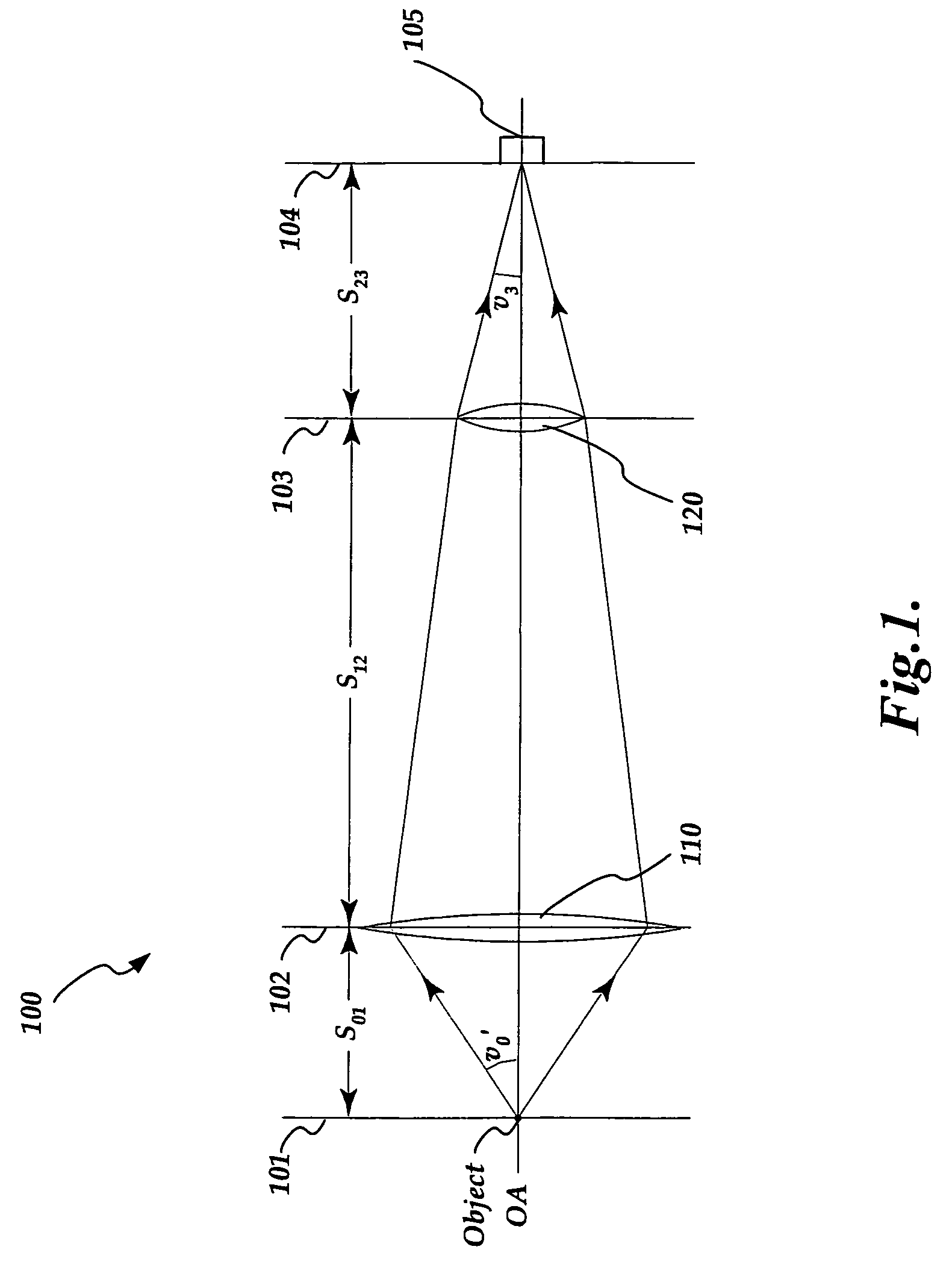
[0017]FIG. 1 is a diagram showing a paraxial thin lens layout of an exemplary variable focal length lens assembly 100. The variable focal length lens assembly 100 can include a first or objective lens 110 and a second or variable focal length lens (VFLL) 120. Both the objective lens 110 and the variable focal length lens 120 are arranged perpendicularly and radially centered along an optical axis OA. The objective lens 110 has a fixed focal length, while the focal length of the VFLL 120 is capable of being changed. As shown in FIG. 1, an object to be viewed is located in an object focus plane 101 on a front side of the variable focal length assembly 100, and an image detection plane 104 is located on a back side of the variable focal length assembly 100. Further, an image detector 105 can be positioned at the image detection plane 104. The image detector may comprise photographic film, or a photodetector array, or any suitable known-now or later-developed image detecting medium.

[001...


PUM


Abstract

Aspects of the invention can provide an imaging device that can include a first optical element having a first focal length, and a second optical element having a variable second focal length. The second optical element can be located at a fixed first distance of approximately the first focal length away from the first optical element. Thus, such an imaging device can permit an optical system to focus on an object at various distances and at a constant magnification with no moving parts.

Description

BACKGROUND[0001]Optical systems that can maintain a constant-magnification image of a viewed object, as a distance of the viewed object from the optical system varies, are useful. Such optical systems have advantages in imaging applications that require recognition or measurement of an object over a range of object distances.[0002]One type of optical system that provides such a capability includes two or more moving optical elements that have a physical distance between them that is mechanically changed to provide an image of the viewed object. For example, U.S. Pat. No. 5,095,388 describes a zoom lens system for photographing objects, located within a broad range of distance, at definite magnification levels. This system is complex, and includes a first and second lens unit, and a first and second mechanism. The first mechanism varies the focal length of the first lens unit and the magnification of the second lens unit, while the second mechanism varies a space between the two lens...

Claims


Application Information

Patent Timeline
IPC IPC(8): H01S3/00G02B9/04
CPCG02B3/14G02B7/08G02B13/24G02B26/005
Inventor FELDMAN, MARK
Owner MITUTOYO CORP
Why Eureka
Try Eureka