
Vehicle radar apparatus and method of controlling the same

Active Publication Date: 2021-05-13
HYUNDAI MOBIS CO LTD
View PDF0 Cites 0 Cited by
  • Summary
  • Abstract
  • Description
  • Claims
  • Application Information

AI Technical Summary

Benefits of technology

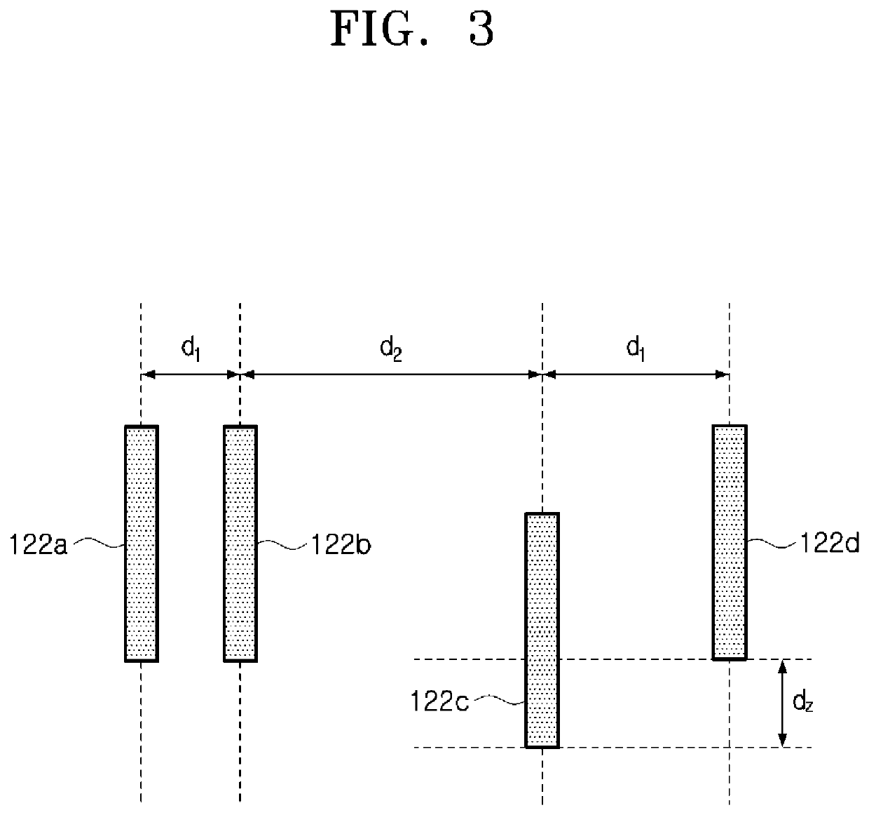
This patent is about estimating the elevation angle of a target using a reception array antenna. By tilting each non-offset reception channel with respect to the azimuth angle of an offset reception channel, the elevation angle can be calculated without needing a separate channel and a receiver. This helps to increase the design degrees of freedom of the antenna array structure and decrease computation time. Essentially, this patent allows for more efficient and accurate target detection without adding size or complexity to the radar apparatus.

Problems solved by technology

However, a vehicle radar apparatus according to the related art operates at a separate channel and includes a receiver in order to calculate an elevation angle, and thus an azimuth angle and the elevation angle are separately calculated, resulting in the disadvantage of increasing the size of the vehicle radar apparatus.

Method used


Image

  • Vehicle radar apparatus and method of controlling the same
  • Vehicle radar apparatus and method of controlling the same
  • Vehicle radar apparatus and method of controlling the same

Examples


Embodiment Construction

[0035]The invention is described more fully hereinafter with reference to the accompanying drawings, in which embodiments of the invention are shown. This invention may, however, be embodied in many different forms and should not be construed as limited to the embodiments set forth herein. Rather, these embodiments are provided so that this disclosure is thorough, and will fully convey the scope of the invention to those skilled in the art.

[0036]As is traditional in the corresponding field, some exemplary embodiments may be illustrated in the drawings in terms of functional blocks, units, and / or modules. Those of ordinary skill in the art will appreciate that these block, units, and / or modules are physically implemented by electronic (or optical) circuits such as logic circuits, discrete components, processors, hard-wired circuits, memory elements, wiring connections, and the like. When the blocks, units, and / or modules are implemented by processors or similar hardware, they may be ...


PUM


Abstract

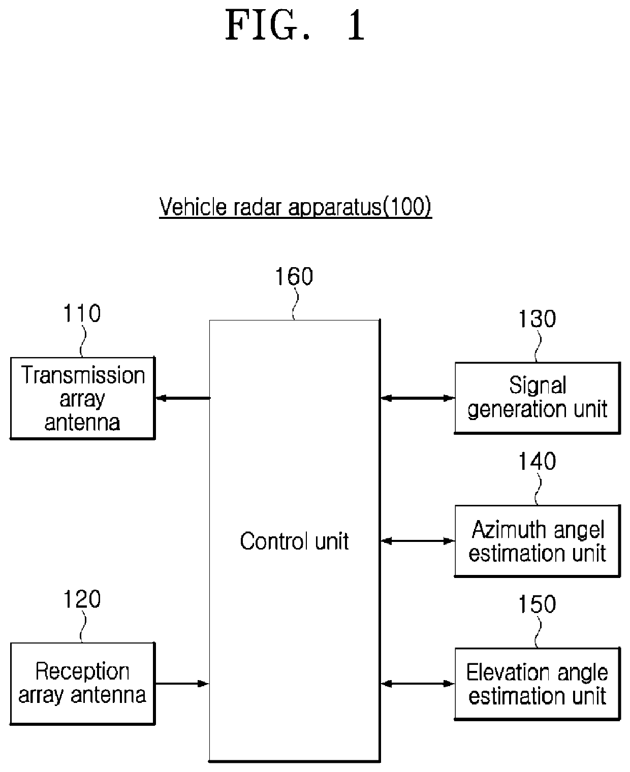
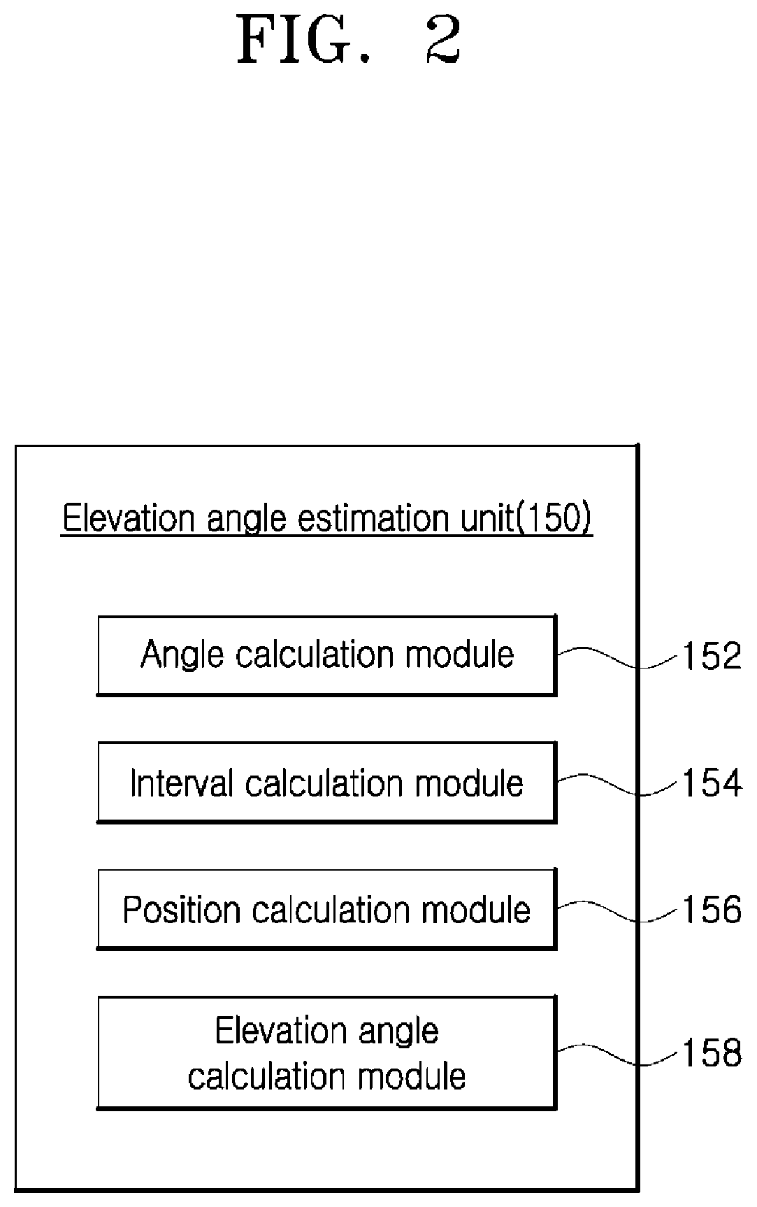
A vehicle radar apparatus and a method of controlling the vehicle radar apparatus, including a transmission array antenna that radiates a radar signal for forward detection; a reception array antenna that operates at N (N is an integer greater than zero) reception channels for receiving the radar signal that is radiated by the transmission array antenna, reflects from a target, and returns; an azimuth angle estimation unit that estimates an azimuth angle of the target using each non-offset reception channel of the N reception channels; and an elevation angle estimation unit that estimates an elevation angle of the target in a diagonal direction in which each non-offset channel of the N reception channels is tilted with respect to an azimuth angle of an offset reception channel thereof.

Description

CROSS-REFERENCE TO RELATED APPLICATION[0001]This application claims priority from and the benefit of Korean Patent Application No. 10-2019-0141555, filed on Nov. 7, 2019, which is herebt by reference for all purposes as if set forth herein.BACKGROUNDField[0002]Exemplary embodiments of the present disclosure relate to a vehicle radar apparatus and a method of controlling the vehicle radar apparatus, and more particularly, to a vehicle radar apparatus and a method of controlling the vehicle radar apparatus, which estimate an elevation angle of a target in a diagonal direction in which each non-offset reception channel of N reception channels at which a reception array antenna operate is tilted with respect to an azimuth angle of an offset reception channel thereof.Discussion of the Background[0003]A radar apparatus emits an electromagnetic wave to an object, receives the electromagnetic wave that reflects from the object, and thus, detects an interval to the object and a direction, a ...

Claims


Application Information

Patent Timeline
IPC IPC(8): G01S13/931G01S13/90G01S7/295
CPCG01S13/931G01S7/295G01S13/9011G01S3/48G01S3/143G01S13/42G01S2013/0254G01S7/35G01S13/68G01S7/352G01S2013/0245
Inventor KIM, SE YOON
Owner HYUNDAI MOBIS CO LTD
Learn More