Unlock instant, AI-driven research and patent intelligence for your innovation.
Implantable medical device which may be controlled from central station
What is Al technical title?
Al technical title is built by PatSnap Al team. It summarizes the technical point description of the patent document.
a central station and medical device technology, applied in the field of implantable medical devices, can solve the problems of inability to accurately predict inability to fully understand the possible programming complexity of the physician who regularly uses such devices, and inability to know the optimal value of some programmable parameters at the tim
Active Publication Date: 2015-08-04
MATOS JEFFREY A
View PDF3 Cites 1 Cited by
Summary
Abstract
Description
Claims
Application Information
AI Technical Summary
This helps you quickly interpret patents by identifying the three key elements:
Problems solved by technology
Method used
Benefits of technology
Benefits of technology
[0015]In a second preferred embodiment, the system of the first embodiment is enhanced by remotely manipulating user biologic features (e.g. the remote control of a light source which causes light to impinge on the user's eye, which in turn causes a change in the size of the user's iris and pupil).
Problems solved by technology
In fact, it is now not uncommon for physicians who regularly use such devices to not be fully versed in all of the possible programming complexities of the devices that they implant.
Furthermore, the optimal value of some programmable parameters cannot be known at the time of device implantation.
Physicians will not uncommonly guess at the values to be programmed for anti-tachycardia pacing, because they may not be able to accurately reproduce the tachycardia that a patient may later have.
Occasionally, the malfunctioning of an implanted device can have very serious consequences.
The Ventritex V-110 defibrillator at one point had a failure mode which resulted in the sudden death of at least one patient.
Such an approach has the obvious limitation of easily breached device security, upon loss, theft, or other unintended acquisition of the device access information.
Method used
Image
Click on the blue label to locate the original text in one second.
Reading with bidirectional positioning of images and text.
Examples
Embodiment Construction
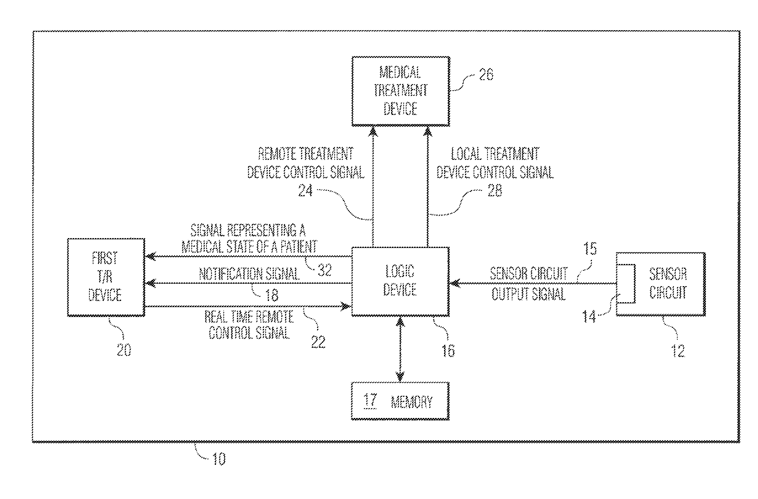
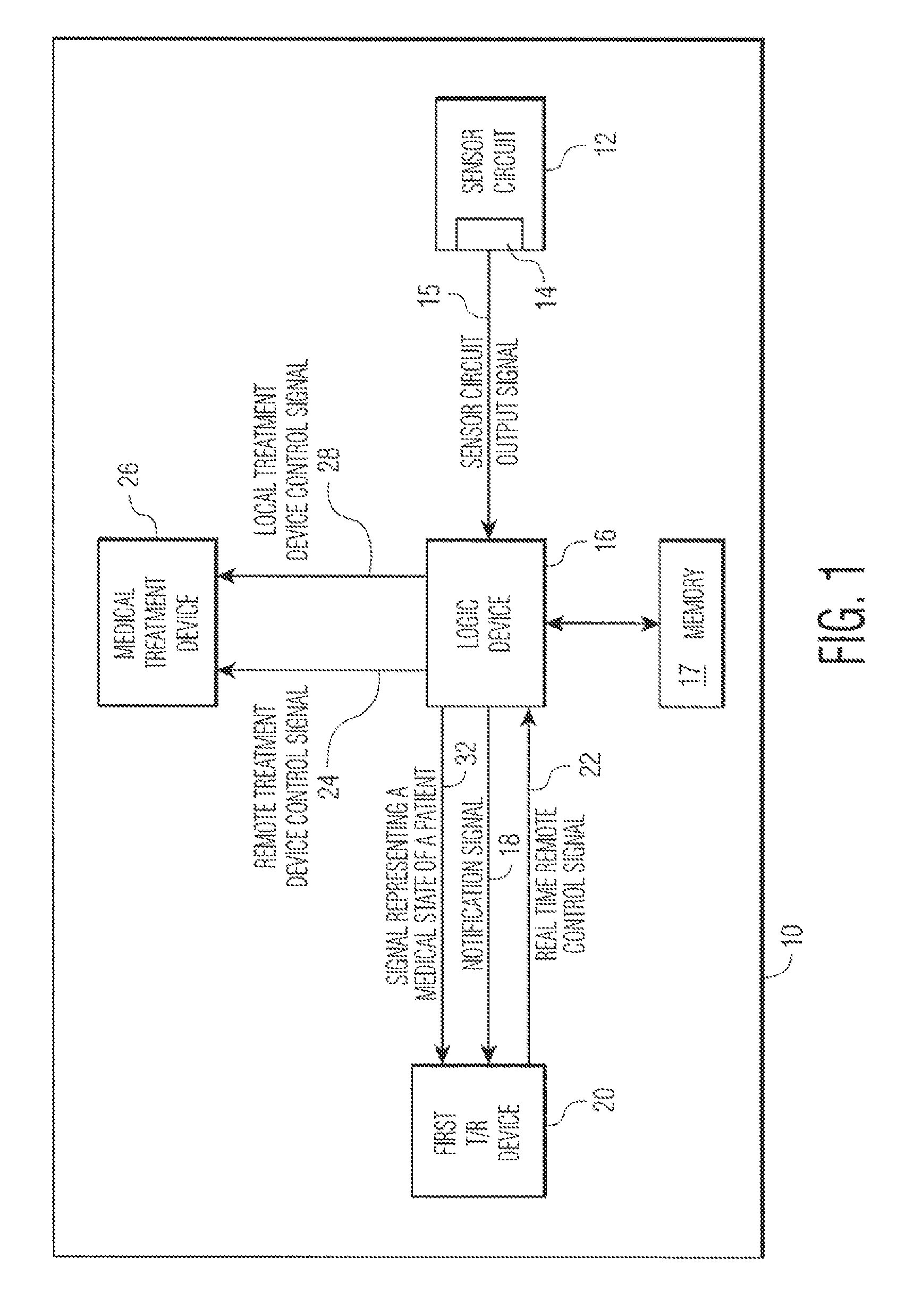
[0057]FIG. 1 shows an implantable medical device 10 which has the capacity to notify a remotely located medical expert. Sensor circuit 12, with output 14, outputs sensor circuit output signals 15. The signals contain data regarding the measurement of at least one medical parameter, a parameter which allows the logic device 16 of the IMD to make treatment decisions. 15 may be an analog signal or a digitized one, as is known in the art. Means for amplification, of 15 and other techniques for signal management as are known in the art, may reside within 12. The sensor circuit is coupled to a sensor, as discussed hereinbelow.
[0058]Logic device 16 analyzes signals 15 to determine if there is a need for (a) treatment of a medical abnormality, and / or (b) notification of a remotely located medical expert. Scenarios are possible in which:
1) the abnormality which calls for notification is the same as that which call for treatment;
2) the abnormality which calls for notification is less severe t...
PUM
Abstract
An implantable medical device (IMD) comprises a transmitting / receiving (T / R) device for transmitting medical data sensed from a patient to, and for receiving control signals from, a medical expert (a human medical professional and / or a computerized expert system) at a remote location; an electronic medical treatment device for treating the patient in response to control signals applied thereto; and a sensor circuit, having a sensor circuit output, for producing sensor circuit output signal(s) representing medical data sensed from the patient. The IMD also includes a logic device (processor) which analyzes the sensor circuit output signal(s) to detect a medical abnormality and, upon detecting an abnormality, either sends a notification signal representing a medical state of said patient to the medical expert at the remote location or sends a local treatment device control signal to the medical treatment device, or does both. The medical expert can transmit an external treatment control signal to the IMD to effect patient treatment, if treatment is warranted. To ensure that the medical expert is authorized to provide such treatment, data which identify one or more authorized medical experts is stored in an IMD memory and compared with identification data transmitted from the putative authorized medical expert along with the external treatment control signal. Only if the identification data received from the putative authorized medical expert matches the pre-stored identification data of an originally authorized medical expert does the IMD effect treatment.
Description
CROSS-REFERENCE TO RELATED PATENTS AND PATENT APPLICATIONS[0001]This application is a continuation-in-part of, and claims priority from, U.S. patent application Ser. No. 14 / 076,521, filed Nov. 11, 2013, which will issue on Aug. 12, 2014 as U.S. Pat. No. 8,805,529 and which, in turn, was a continuation of the U.S. patent application Ser. No. 13 / 795,250 filed Mar. 12, 2013 and which issued on Nov. 12, 2013, as U.S. Pat. No. 8,583,251. This grandparent application, in turn, was a continuation of, and claimed priority from, the U.S. patent application Ser. No. 12 / 154,079, filed May 19, 2008, which issued on Jun. 25, 2013 as U.S. Pat. No. 8,214,043 and which, in turn, claimed priority from the Provisional Application No. 60 / 930,525 filed May 17, 2007.[0002]The subject matter of this application is also related to that of U.S. Pat. Nos. 7,277,752; 8,214,043; 8,233,672; 8,565,882; 8,655,450 and 8,706,225; and U.S. patent application Ser. No. 11 / 502,484, filed Aug. 10, 2006; U.S. patent app...
Claims
Application Information
Patent Timeline
Application Date:The date an application was filed.
Publication Date:The date a patent or application was officially published.
First Publication Date:The earliest publication date of a patent with the same application number.
Issue Date:Publication date of the patent grant document.
PCT Entry Date:The Entry date of PCT National Phase.
Estimated Expiry Date:The statutory expiry date of a patent right according to the Patent Law, and it is the longest term of protection that the patent right can achieve without the termination of the patent right due to other reasons(Term extension factor has been taken into account ).
Invalid Date:Actual expiry date is based on effective date or publication date of legal transaction data of invalid patent.
