Multipurpose tool configured to facilitate access to individual tool members

a multi-purpose tool and tool member technology, applied in the field of tools, can solve the problems of reducing or breaking the bias force provided by the spring, affecting the identification of the particular tool member relative to the other tool, and disadvantageous wear, so as to facilitate identification and selection, improve the access to individual tool members

Active Publication Date: 2015-08-04
LEATHERMAN TOOL GROUP
View PDF9 Cites 6 Cited by
  • Summary
  • Abstract
  • Description
  • Claims
  • Application Information

AI Technical Summary

Benefits of technology

[0007]According to embodiments of the present invention, a tool, such as a multipurpose tool, is provided that is configured to provide improved access to individual tool members. In this regard, the tool of one embodiment may facilitate the identification and selection of a respective tool member and the subsequent unfolding of the tool member. In another embodiment, a tool may be provided that has a more structurally secure guard for one or more of the tool members.
[0010]In accordance with another embodiment, a multipurpose tool is provided that includes a plurality of handles configured for relative movement between a closed position and an open position. The plurality of handles include a first handle defining a longitudinally extending axis. The multipurpose tool also includes a plurality of tool members carried by at least a first handle and foldable into the first handle. Each tool member of this embodiment includes a designation representative of the respective tool member. The designations of the tool members are differently positioned along the longitudinally extending axis. At least one of the tool members may define a notch aligned along the longitudinally extending axis with the designation of an adjacent tool member. Additionally or alternatively, the first handle may include a pair of opposed sidewalls that define a channel into which the plurality of tool members are foldable. In this embodiment, a sidewall of the first handle may define a window aligned along the longitudinally extending axis with the designation of at least one of the tool members. As such, a user may more confidently select a respective tool member from among the plurality of tool members folded into the handle based upon the designations carried by the tool members.
[0013]In yet another embodiment, a tool is provided that includes a first handle having first and second sidewalls and a channel defined therebetween, a tool member attached to an exterior surface of the first sidewall of the first handle and foldable relative thereto between a closed position and an open position, and a guard operably connected to the first handle. The guard of this embodiment includes an upstanding portion and a laterally extending portion with the tool member disposed between the first sidewall of the first handle and the guard in an instance in which the tool member is in the closed position. A distal edge of the laterally extending portion of the guard of this embodiment extends at least to an inner surface of the first sidewall of the first handle proximate the channel. In one embodiment, the distal edge of the laterally extending portion of the guard is aligned with the inner surface of the first sidewall of the first handle proximate the channel. As a result, the guard may be more securely affixed to the handle.

Problems solved by technology

Over time and with repeated movement between the open and closed positions, the spring that biases the pliers or scissors toward an open position may disadvantageously become worn such that the bias force provided by the spring is reduced or break.
As a number of tool members may be folded into the handles and since the visibility of the tool members within the handle is relatively limited, it may be difficult to identify a particular tool member relative to the other tool.
Because of the limited space available within the handles, it may also be difficult to engage a particular one of the tool members in an effort to unfold or open the tool member.

Method used


Image

  • Multipurpose tool configured to facilitate access to individual tool members
  • Multipurpose tool configured to facilitate access to individual tool members
  • Multipurpose tool configured to facilitate access to individual tool members

Examples


Embodiment Construction

[0029]The present inventions now will be described more fully hereinafter with reference to the accompanying drawings, in which some, but not all embodiments of the inventions are shown. Indeed, these inventions may be embodied in many different forms and should not be construed as limited to the embodiments set forth herein; rather, these embodiments are provided so that this disclosure will satisfy applicable legal requirements. Like numbers refer to like elements throughout.

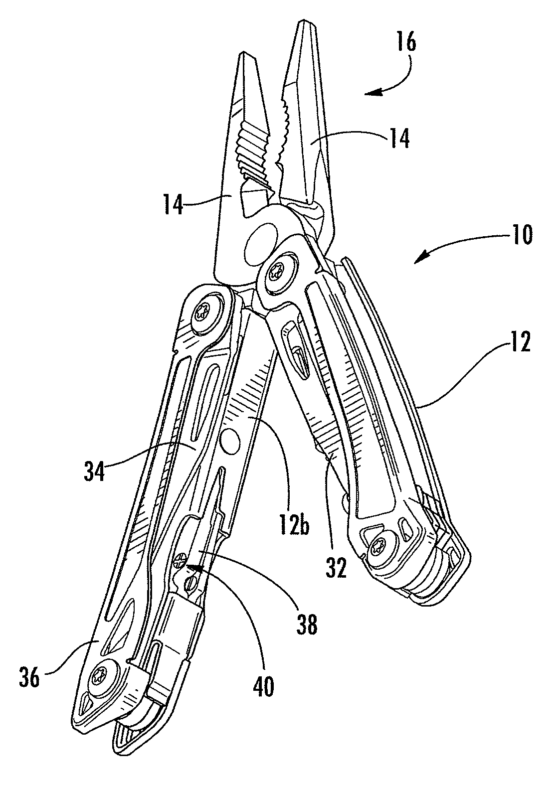
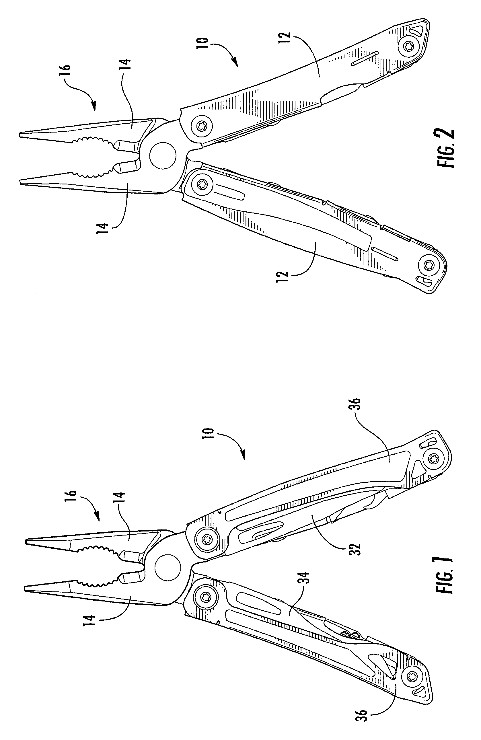
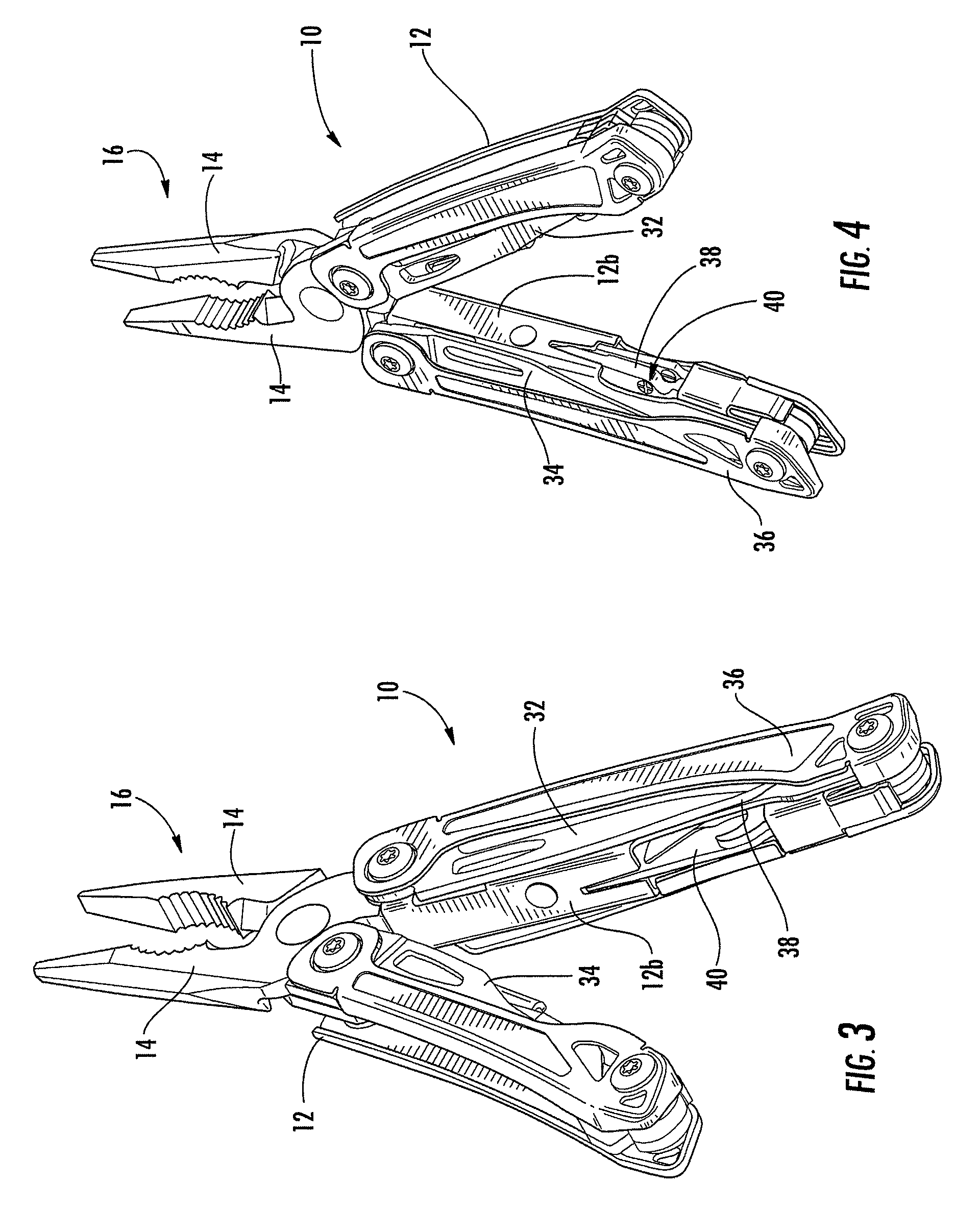
[0030]Referring now to FIGS. 1-8, a tool, such as a multipurpose tool 10, according to one embodiment of the present invention is depicted. While the tool will be described in the context of a multipurpose tool, other types of tools may readily employ embodiments of the present invention including knives and other tools that are not considered multipurpose tools. For purposes of illustration, but not of limitation, a multipurpose tool employing an embodiment of the present invention will now be described.

[0031...


PUM


Abstract

A multipurpose tool is provided that is configured to provide ready access to individual tool members. In this regard, the tool may facilitate the identification and selection of a respective tool member and the subsequent unfolding of the tool member. The tool is also provided that has a structurally secure guard for one or more of the tool members, such as a knife blade.

Description

FIELD[0001]Embodiments of the present invention relate generally to tools and, more particularly, to a tool, such as a multipurpose tool, configured to facilitate access to individual tool members and a tool, such as a multipurpose tool, that includes a structurally secure guard for one or more of the tool members.BACKGROUND[0002]Multipurpose tools are widely popular for their utility in a substantial number of different applications. As its name suggests, a multipurpose tool includes a number of tool members carried by common frame. A multipurpose tool may include different combinations of tool members depending upon its intended application. For example, multipurpose tools that are designed for a more universal or generic application can include pliers, a wire cutter, a bit driver, one or more knife blades, a saw blade, a bottle opener or the like. Other multipurpose tools are designed to service more specific applications or niche markets and correspondingly include tool members ...

Claims


Application Information

Patent Timeline
Patent Type & Authority Patents(United States)
IPC IPC(8): B25B7/22B25F1/00B25F1/02B25F1/04
CPCB25F1/003B25F1/04B25F1/02B25B7/22
Inventor PURNOMOHADI, ANDRORIVERA, BENJAMIN C.BARNES, BLAIR SCOTT
Owner LEATHERMAN TOOL GROUP
Why Eureka
Try Eureka