Adapter device to couple an endoscope with a medical appliance

a technology of adapter device and endoscope, which is applied in the direction of mechanical equipment, applications, instruments, etc., can solve the problems of reducing light yield and difficult handling, and achieve the effects of low cost, high reliability, and high production efficiency

Active Publication Date: 2015-08-11
KARL STORZ GMBH & CO KG
View PDF9 Cites 0 Cited by
  • Summary
  • Abstract
  • Description
  • Claims
  • Application Information

AI Technical Summary

Benefits of technology

[0011]An advantage of the form-locked connection for the adapter device in a predetermined angle position relatively to the coupling device on the medical appliance consists in the fact that the adapter device can be replaced without adjustment being necessary. Replacement of the adapter device can thus be undertaken by a technical layperson without disadvantageous consequences for the optical coupling between the endoscope and the medical appliance. As a result, considerable costs can be spared for sending the medical device to the producer for replacement and adjustment of the adapter device by the producer, and for shipping the medical appliance back to the owner. Besides these costs, there is a saving in terms of the corresponding downtime of the medical appliance. While the appliance is unavailable to the owner for at least a few days in the event of a conventional replacement with subsequent adjustment by the producer, with the present invention an exchange of the adapter device is possible within a few seconds or minutes and with correspondingly minimal costs. The medical appliance is immediately available again without restriction.
[0012]In addition, it becomes possible to avoid the disadvantages of the aforementioned auxiliary adapter for coupling a light conductor cable on a coupling device, which is primarily intended and configured for direct coupling with a proximal end of the endoscope. With an exchange of the adapter device on a medical appliance that can be executed easily and quickly, an alternative and alternating possibility is the coupling of the proximal end of the endoscope on the medical appliance. The coupling in particular can be optimal since it avoids transmission losses or a reduction of the light gain through an additional adapter.
[0016]A fastening screw-on sheath can comprise a fastening device that is especially cost-effective to produce and at the same time is robust and reliable. A fastening screw-on sheath can be configured in such a way that it can also be operated intuitively by technically non-practiced medial personnel and thus quickly and reliably without time-intensive training.
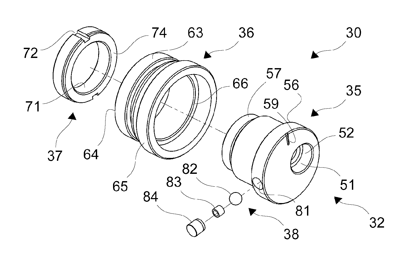
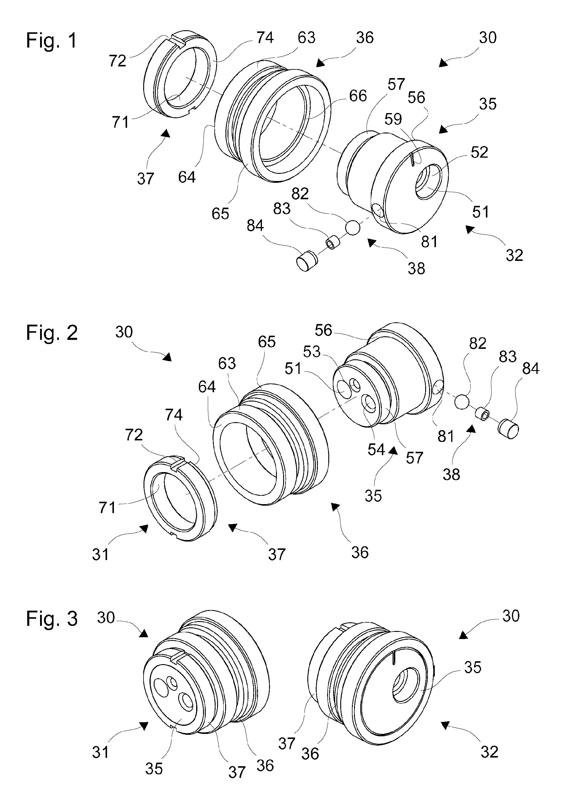
[0017]A three-part structure of the adapter device, consisting of adapter body, fastening screw-on sheath and a screw-nut that secures the fastening screw-on thread on the adapter body, can offer a particularly useful combination of low production costs, mechanical robustness, and precision. The adapter body, the fastening screw-on sheath and the screw-nut, in particular, can each be manufactured of stainless steel or another metallic or non-metallic material in simple manner by turning, milling and boring.
[0018]An adapter device as described here, in addition, can comprise a marker on the side of the adapter body facing the endoscope to indicate a foreseen angle position of the adapter body with respect to the medical appliance. Such a marking can simplify insertion and securing of the adapter body on a medical appliance.
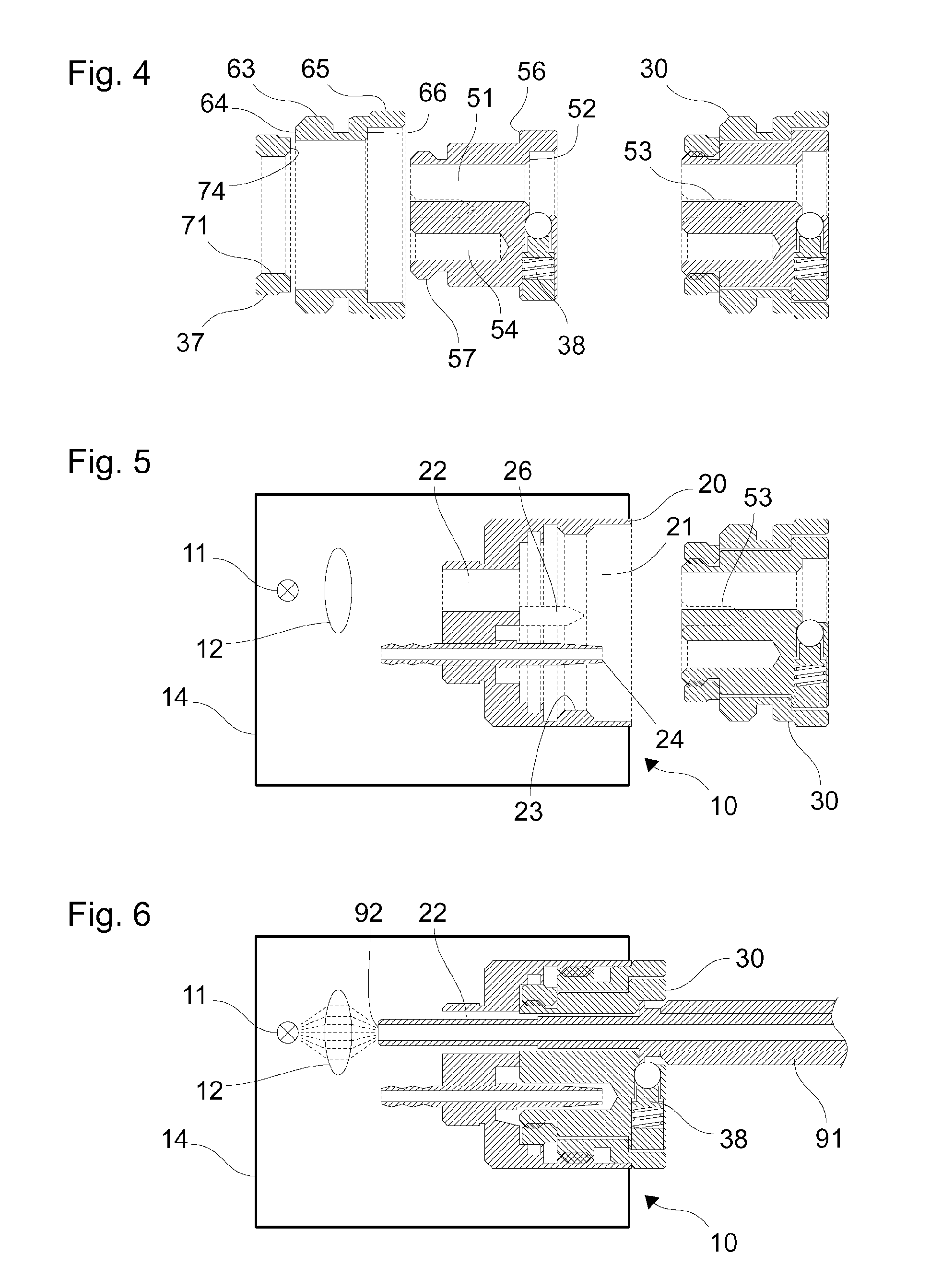
[0022]An adapter set includes an adapter device in which the through-hole as described above is configured to insert a proximal end of a coupling of a light conductor cable and an adapter device as described above is configured to insert a coupling on a proximal end of an endoscope. The adapter devices of the adapter set, alternatively, can be secured on a medical appliance. Because of the form-locked securing of a predetermined angle position of the adapter body with respect to the medical appliance, the adapter devices can be exchanged with one another simply without requiring an adjustment and thus quickly. While one of the two adapter devices makes possible an optimal direct coupling between a medical appliance and an endoscope, the other allows an optimal coupling of the medical appliance and the endoscope via a light conductor cable or only the coupling of the medical appliance with a light conductor cable. The coupling here is optimal, in particular with respect to low light losses or a high transmission and / or with respect to convenience of operation.

Problems solved by technology

This auxiliary adapter, however, clearly reduces the light yield and makes handling difficult.

Method used


Image

  • Adapter device to couple an endoscope with a medical appliance
  • Adapter device to couple an endoscope with a medical appliance
  • Adapter device to couple an endoscope with a medical appliance

Examples


Embodiment Construction

[0037]FIGS. 1 through 3 show schematic axonometric depictions of the components of a first adapter device or of the assembled first adapter device. FIG. 4 shows schematic sectioned depictions of the first adapter device. At the left in FIG. 4, the three main components of the first adapter device are shown separately, similarly as in FIGS. 1 and 2, and at the right the first adapter device is shown assembled or installed. The illustrated section planes each contain the longitudinal axis of the adapter device.

[0038]The first adapter device 30 comprises a side that is to face a medical appliance or a proximal side 31 (compare FIG. 2 and FIG. 3, right) and a side that is to face a light conductor cable or an endoscope or a distal side 32 (compare FIG. 1 and FIG. 3, right). The first adapter device 30 includes an adapter body 35, a fastening screw-on sheath 36, and a screw-nut 37. A catch-lock device 38 is integrated into the adapter body 35. The adapter body 35, fastening screw-on shea...


PUM


Abstract

An adapter device, which is configured to couple an endoscope with a medical appliance, such that the medical appliance is provided to generate light to illuminate an object to be investigated by an endoscope, includes an adapter body with a through-hole through which light generated by the medical appliance can be transmitted, and a fastening device to removably secure the adapter body on the medical appliance. The side of the adapter body that is to face the medical appliance is configured to be held form-locked in a predetermined angle position when the adapter body is secured on the medical appliance.

Description

CROSS-REFERENCE TO RELATED APPLICATIONS[0001]The present application claims priority of German patent application No. 10 2009 056 107.2 filed on Nov. 30, 2009, the content of which is incorporated herein by reference.FIELD OF THE INVENTION[0002]The present invention relates to an adapter device to couple an endoscope with a medical appliance, where the medical appliance is configured to generate light to illuminate an object that is to be investigated by means of an endoscope and on a medical appliance.BACKGROUND OF THE INVENTION[0003]In medical (human and veterinarian medical) and non-medical, technical applications of an endoscope, as a rule a light source is required to illuminate the observed body cavity. The light source is, for example, a halogen incandescent lamp or a xenon high-pressure gas-discharge lamp. The light source together with devices for power supply, control or regulation and a user interface is positioned in a housing. A proximal end of an endoscope can be coupl...

Claims


Application Information

Patent Timeline
Patent Type & Authority Patents(United States)
IPC IPC(8): A61B1/04G02B23/24A61B1/06H04N9/47H04N7/18F16L27/00H01R13/62A61B1/00A61B1/07
CPCA61B1/00128A61B1/0669A61B1/07G02B23/2476A61B1/00126
Inventor GEISSER, ROMANAHENSLER, FRITZ
Owner KARL STORZ GMBH & CO KG
Why Eureka
Try Eureka