Stator for an electric machine

a technology for electric machines and stators, which is applied in the direction of dynamo-electric machines, synchronous generators, electrical apparatus, etc., can solve the problems of wound wire insulation, damage to the insulation between the connection conductors, and outage of the stator

Inactive Publication Date: 2003-09-18
ZF SACHS AG
View PDF9 Cites 21 Cited by
  • Summary
  • Abstract
  • Description
  • Claims
  • Application Information

AI Technical Summary

Problems solved by technology

In one of the joined connections mentioned above, it is disadvantageous that the process heat introduced for connecting can result in damage to the insulation between the connection conductors and, further, to the insulation of the wound wires in the area of the coils.
This can lead very quickly to unwanted short circuiting which influences the operation of the electric machine and can even lead its outage.
Vibrations which occur during the operation of the electric machine or which act on the latter from the outside lead to mechanical alternating loads on the electrical connections of the machine which can loosen within a short period of time.
Winding around the terminal extensions is a typical manual work step which impedes increased efficiency in the manufacture of such stators.
Because of the relatively large number of coil ends, there is a considerable risk of faulty connections in the wiring of the coils of a stator due to incorrect allocation to the connection conductors.
Even when great caution is exercised in this regard, 100 percent certainty can not be achieved in the manufacture of stators.
In this way, the assembly steps comprising mechanical fixation of the connection conductors and electrical connection of the latter to the coil ends, which were originally two independent assembly steps, are combined in one individual step so that considerable time and cost are saved in the production of the stator.

Method used


Image

  • Stator for an electric machine
  • Stator for an electric machine
  • Stator for an electric machine

Examples


Embodiment Construction

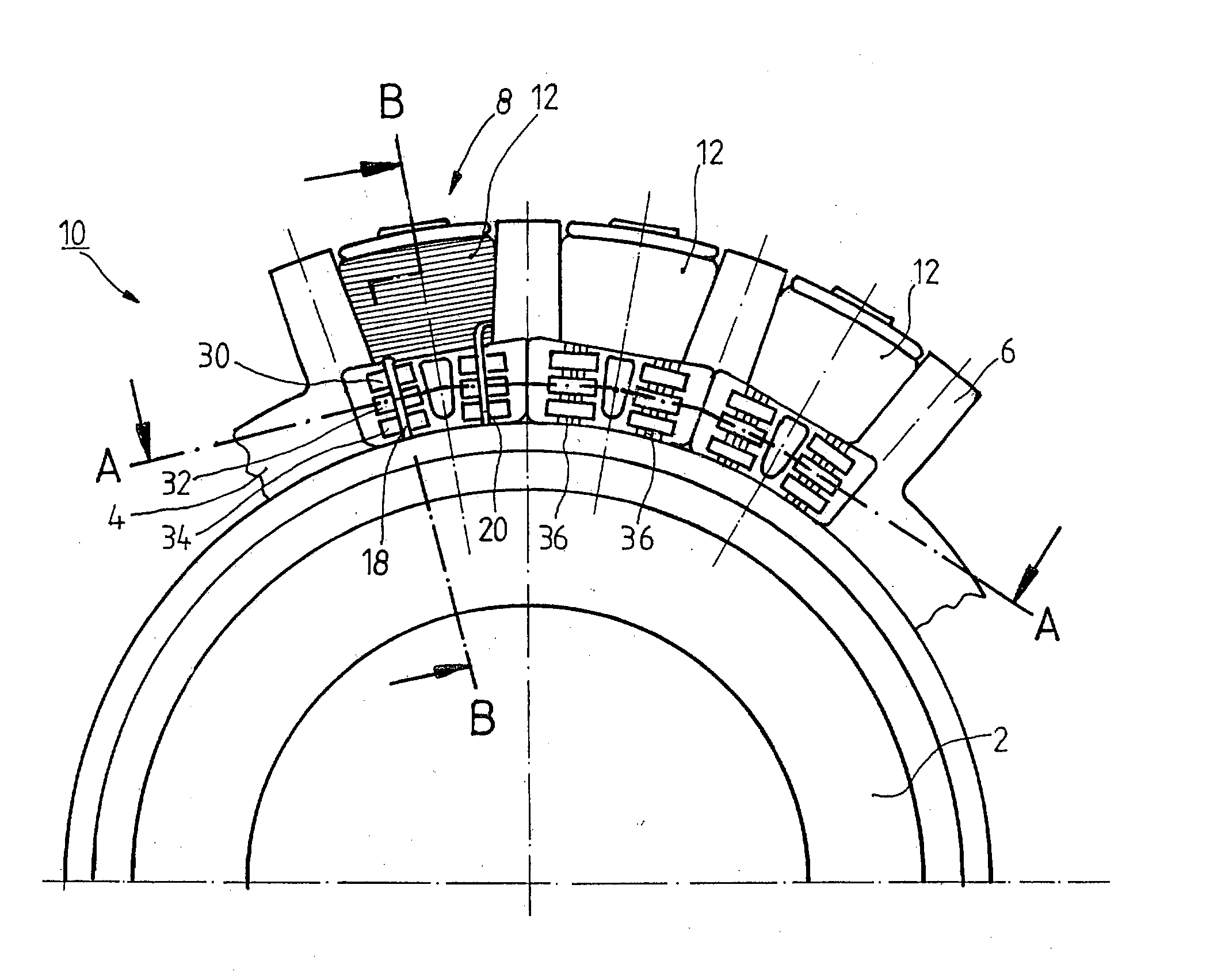
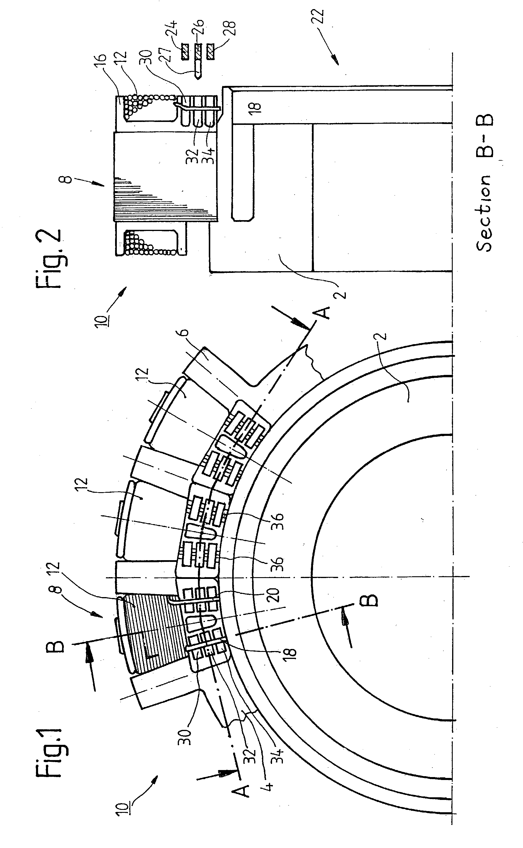
[0047] FIG. 1 shows a stator 10 mounted on a cooled hub 2 for an electric machine, not shown in more detail, with an annular stator yoke 4 comprising electric sheet metal laminations. The specific construction of the electric machine is not relevant to the following description. For example, the electric machine can be a permanently excited synchronous machine, an induction motor, a reluctance generator in internal rotor construction, external rotor construction or pancake construction, or some other kind of electric machine. The stator yoke 4 has, in circumferential direction, a quantity of teeth 6 which are directed radially outward, every second tooth 6 being fitted with an individual coil 8. The coils 8 comprise a winding 12 of an individual conductor or multiwire conductor whose individual conductors can be twisted together. In FIG. 1, the individual coils 8 were wound separately in a previous manufacturing step by means of bobbins 16 comprising an insulating material and were ...


PUM


Abstract

A plurality of stator coils having coil ends are arranged on an annular stator yoke. Concentrically arranged connection conductors which are electrically insulated relative to one another have laterally projecting terminals for connecting to the ends of the stator coils. Receiving chambers arranged about the front side of the stator yoke receive the terminals of the connection conductors and fix the connection conductors in position. The receiving chambers are allocated to the coil ends which form an electric clamping connection by pairs with the terminals of the connection conductors at the receiving chambers.

Description

[0001] 1. Field of the Invention[0002] The invention is directed to a stator for an electric machine with a ring-shaped stator yoke at which a plurality of stator coils having coil ends are arranged, and with a wiring arrangement for the stator coils at a front side of the stator yoke, wherein the wiring arrangement has connection conductors which are electrically insulated relative to one another and are concentric to one another. The invention also relates to methods for producing a wiring arrangement of a stator.[0003] 2. Description of the Related Art[0004] Known stators for electric machines have a stator yoke with a quantity of stator teeth which hold the electric winding, e.g., in the form of individual stator coils which are wound from an insulating wire. The ends of the coils are associated with individual strands and are wired together in a predetermined manner by shared connection conductors. In three-phase generators, the stator has three strands and, therefore, at least...

Claims


Application Information

Patent Timeline
Patent Type & Authority Applications(United States)
IPC IPC(8): H02K3/52H02K3/50
CPCH02K2203/09H02K3/522
Inventor OPPITZ, HORST
Owner ZF SACHS AG
Why Eureka
Try Eureka