A Plugging Tool, and Method of Plugging a Well

a well and tool technology, applied in the direction of vibration devices, earthwork drilling and mining, borehole/well accessories, etc., can solve the problems of many rig days, pipe sticking, and complex procedure of swarf handling, so as to improve cement flow and bonding, and save time and cost. , the effect of improving the bonding

Active Publication Date: 2018-09-06
WELLGUARD AS
View PDF3 Cites 20 Cited by
  • Summary
  • Abstract
  • Description
  • Claims
  • Application Information

AI Technical Summary

Benefits of technology

[0047]The invented plugging tool is modular and capable of performing all necessary downhole tasks in one trip. This results in a considerable time and cost savings, compared to the prior art methods. The plugging is performed without damaging or deforming the well casing walls, which means that casing holes can be temporarily plugged for pressure testing during the procedure. The ability to perforate the casing without damaging the casing wall per se, also enables CBL logging (Cement Bond Log) to verify the condition of the annulus cement before the internal volume is filled with cement. The vibrating device on the invented tool also improves cement flow and bonding.

Problems solved by technology

Large volume of swarf (debris or waste resulting from the milling) is produced, and handling the swarf is a complex procedure.
Disadvantages of the section casing milling method include:Time consuming, many rig days (ca.
21-30 days for a 100 m plug);Risk of swarf and debris handling;Potential for swarf damaging the blow-out preventer (BOP);Risk of pipe getting stuck due to poor hole cleaning (because of swarf);Several trips are required to change the mill.
Disadvantages with this technique include:It is difficult to verify new annulus cement as the perforation is plugged by cement which remains below the cement retainer;Multiple trips required.
Disadvantages associated with the co-called PWC technology include:May damage the casing;Unable to perform cement bond log (CBL);Unable to verify new annulus cement barrier;Extended operation time; multiple trips required (typically four trips for a 100 m plug);Use of explosives;Extreme caution may be necessary (nearby producer wells may have to be shut off).
All of the above methods a)-d) have challenges relating to conforming the cement over the full interval, this relates both to the placing as well as the logging.
Some of the cement will flow through a bypass section to power the devices and cause vibrations in the casing steel.
Being mechanical devices, the techniques are limited in frequency selection and bandwidth.

Method used


Image

  • A Plugging Tool, and Method of Plugging a Well
  • A Plugging Tool, and Method of Plugging a Well
  • A Plugging Tool, and Method of Plugging a Well

Examples


Embodiment Construction

[0063]The following description will use terms such as “horizontal”, “vertical”, “lateral”, “back and forth”, “up and down”, “upper”, “lower”, “inner”, “outer”, “forward”, “rear”, etc. These terms generally refer to the views and orientations as shown in the drawings and that are associated with a normal use of the invention. The terms are used for the reader's convenience only and shall not be limiting.

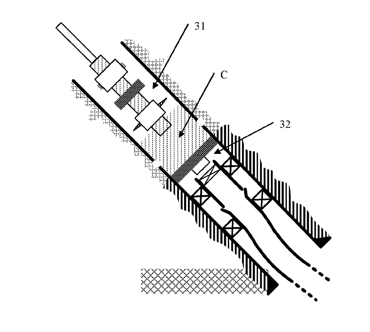
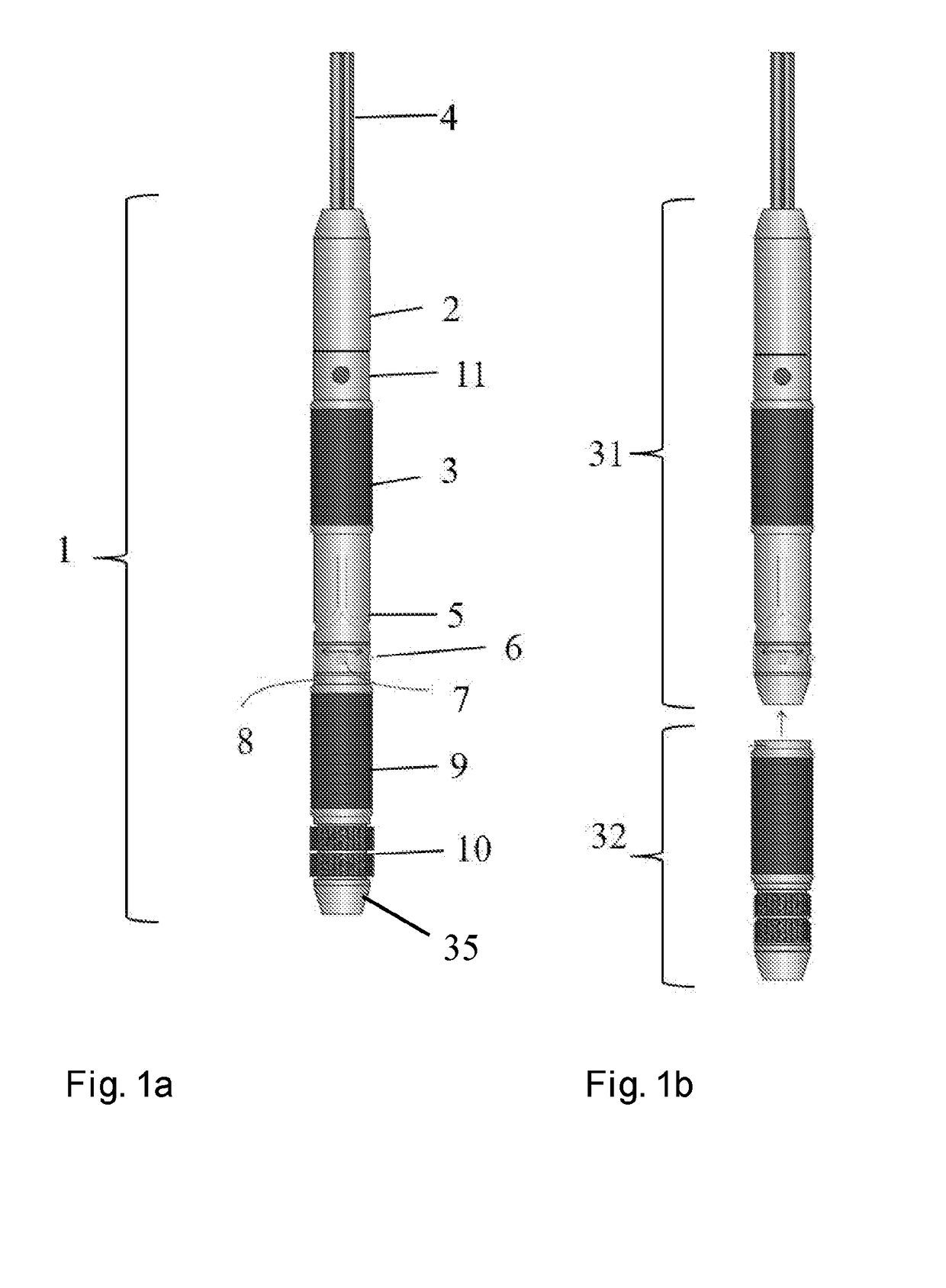
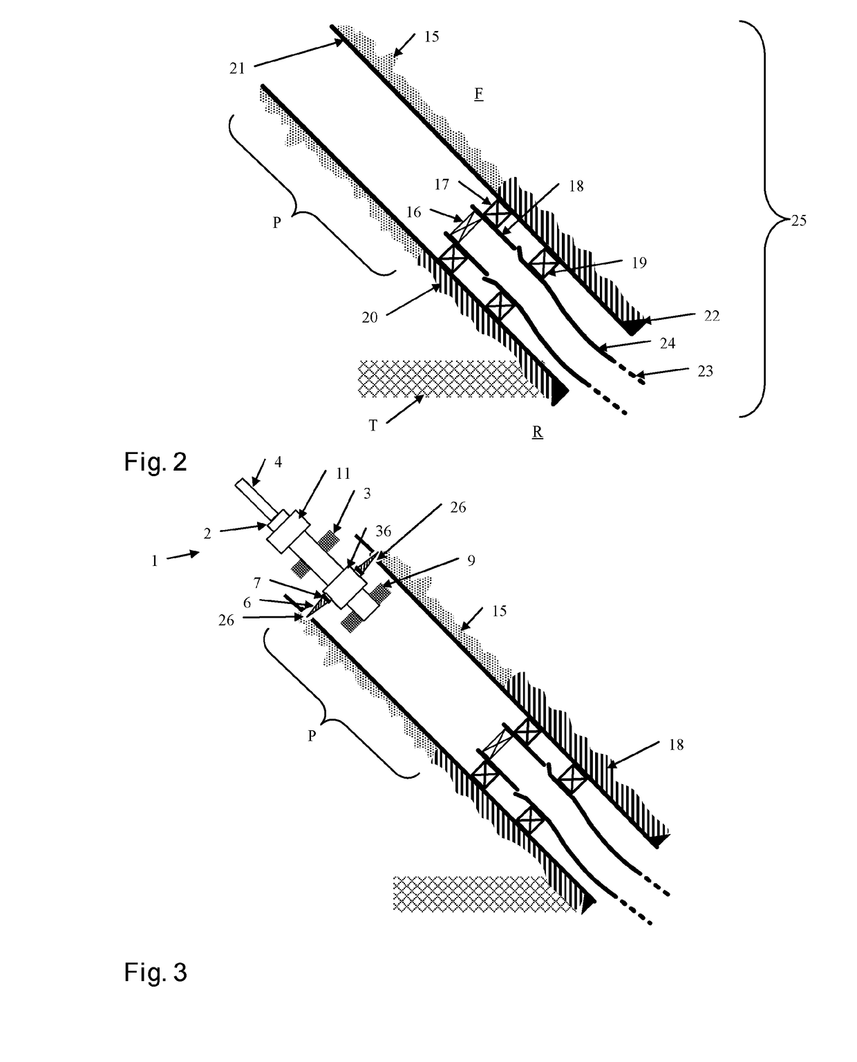
[0064]FIG. 1a and FIG. 1b show an embodiment of the invented plugging tool 1. The plugging tool is conveyed (in the casing) and controlled via coiled tubing 4. The plugging tool comprises two main sections 31, 32, releasably interconnected by a quick-disconnect mechanism 8 (which per se is known in the art). In FIG. 1b, the lower section is referred to as a non-retrievable section 32 and the upper section is referred to as a retrievable section 31.

[0065]The plugging tool comprises a vibration generator 2 and a mechanical actuator 11. The vibration generator 2 may be based on magnetos...


PUM


Abstract

The present invention relates to a method of plugging a petroleum well permanently or temporary, for instance, during a plug and abandonment operation (P&A) or during other operations where setting of a barrier in the well is required, by the use of a multitask tool. The multitasking nature enables the making and sealing verification of a plug in one trip. The multitasking tool (1) comprising interconnected releasable sections (31, 32), each comprising at least one packer arrangement (3, 9), perforating means (6, 36) and a vibration device (2).

Description

FIELD OF THE INVENTION[0001]The invention concerns the field of plugging tubular members. More specifically, the inventions concerns a tool and a method of plugging a hydrocarbon well permanently or temporary, for instance, during a plug and abandonment operation (P&A) or during other operations where the setting of a barrier in the well is required.BACKGROUND OF THE INVENTION[0002]Hydrocarbon fluids such as oil and natural gas are obtained from a subterranean geologic formation, referred to as a reservoir, by drilling a well that penetrates the hydrocarbon-bearing formation. Once a wellbore has been drilled, the well must be completed before hydrocarbons can be produced from the well. A completion involves the design, selection, and installation of equipment and materials in or around the wellbore for conveying, pumping, or controlling the production or injection of fluids. After the well has been completed, production testing of the well can begin.[0003]Hydrocarbon wells for the e...

Claims


Application Information

Patent Timeline
Patent Type & Authority Applications(United States)
IPC IPC(8): E21B33/134E21B33/124E21B28/00
CPCE21B33/134E21B33/124E21B28/00E21B33/13E21B29/00
Inventor ABDOLLAH, JAFARCARLSEN, INGE MANFREDFLO, RUNENYHAVN, FRIDTJOFESPE, EIRIK
Owner WELLGUARD AS
Why Eureka
Try Eureka