
Slide bearing and method for the production thereof

a technology of slide bearings and bearing pins, which is applied in the direction of bearings, shafts, engine lubrication, etc., can solve the problems of complex production of slide bearings, inability to loosen bearing pins subsequently, and the appearance of corrugated profiles becoming plasti

Inactive Publication Date: 2003-11-18
GLEITLAGER
View PDF5 Cites 25 Cited by
  • Summary
  • Abstract
  • Description
  • Claims
  • Application Information

AI Technical Summary

Benefits of technology

The object of the present invention is to improve a slide bearing of the type described above with the aim of being able to insert the bearing pin into the already pressed-in flange bearing bushing, prior to assembly of the components forming the hinge, and retain it there captive, so that virtually one hinge half can be handled together with the bearing pin.
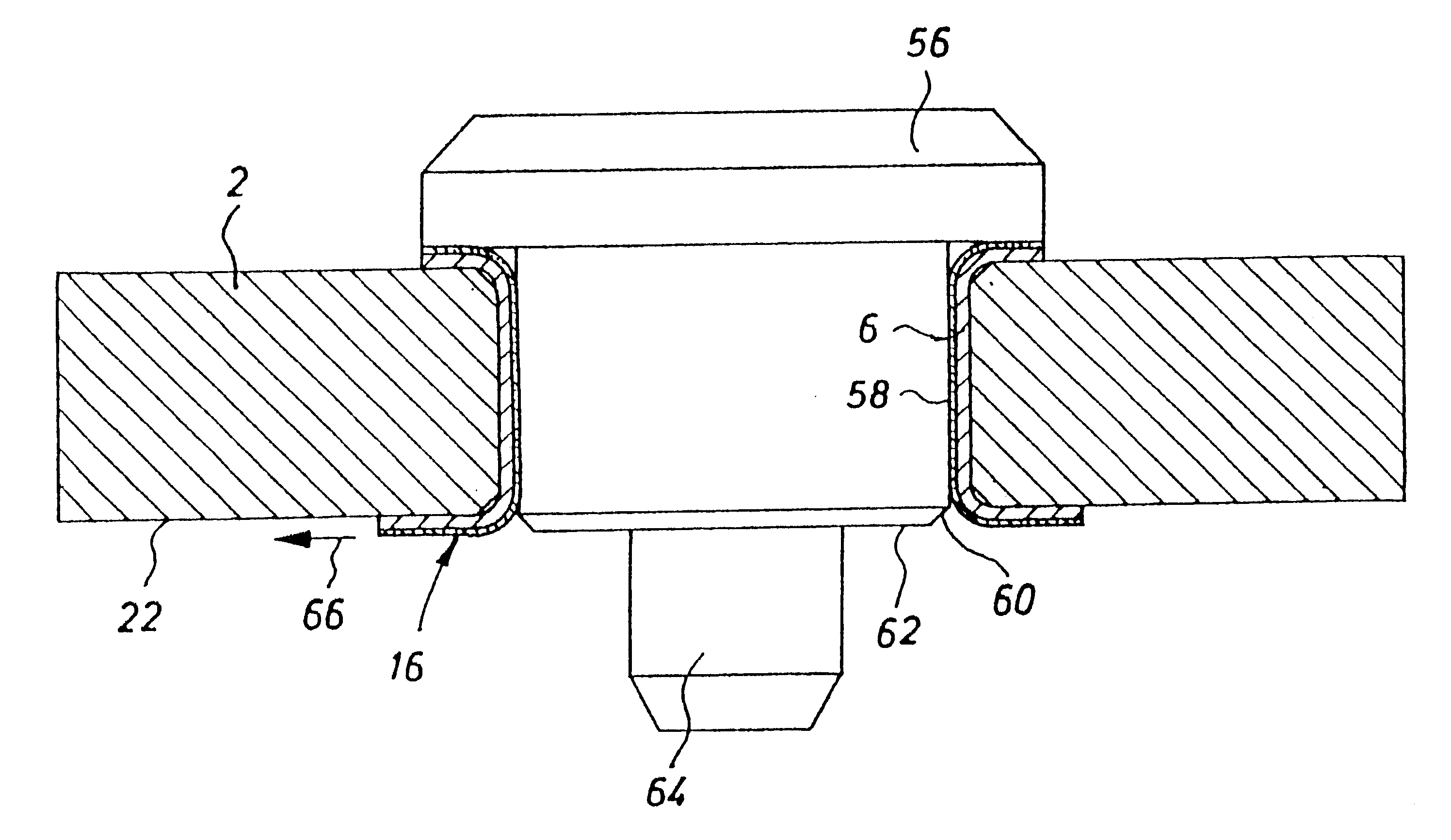
As a result of the flange-bearing bushing pressed into the bearing opening having the inward protruding projection around the radius, which is preferably elastically deformable radially outwards, a clearance-free slide bearing or seating of the bearing pin in the flange-bearing bushing can be achieved on the one hand when the bearing pin is inserted; on the other hand, when the bearing pin is inserted into the flange-bearing bushing, it is a pinch fit in the flange-bearing bushing. The hinge housing component can therefore be warehoused, transported and brought to final assembly in a more or less pre-assembled state. As a result, assembly on site can be designed to be considerably more efficient. The cost savings are considerable. It must be pointed out that the shape of the crimped projection in the form of the curved profile of the flange-bearing bushing is selected in such a way that the aforementioned clearance between the bearing opening of the hinge housing component and the outer wall of the flange-bearing bushing is preferably closed in the curved area following insertion of the bearing pin, meaning that the flange-bearing bushing contacts the bearing opening with its outer surface, which is once more cylindrical.
As was already mentioned initially, it proves advantageous if the slide bearing comprises a pre-assembled hinge housing component, into whose bearing opening a flange-bearing bushing is pressed, with the bearing pin retained captive therein. The term "captive" is not to be understood in the sense that the bearing pin could not be pressed out of the flange-bearing bushing again in the opposite direction to its insertion. Rather, it is a pinch fit, or interference fit, in the bearing opening as a result of the radial deformation of the curved area of the flange-bearing bushing, so that it does not fall out of the bushing inadvertently and unintentionally during normal handling of the hinge housing component.
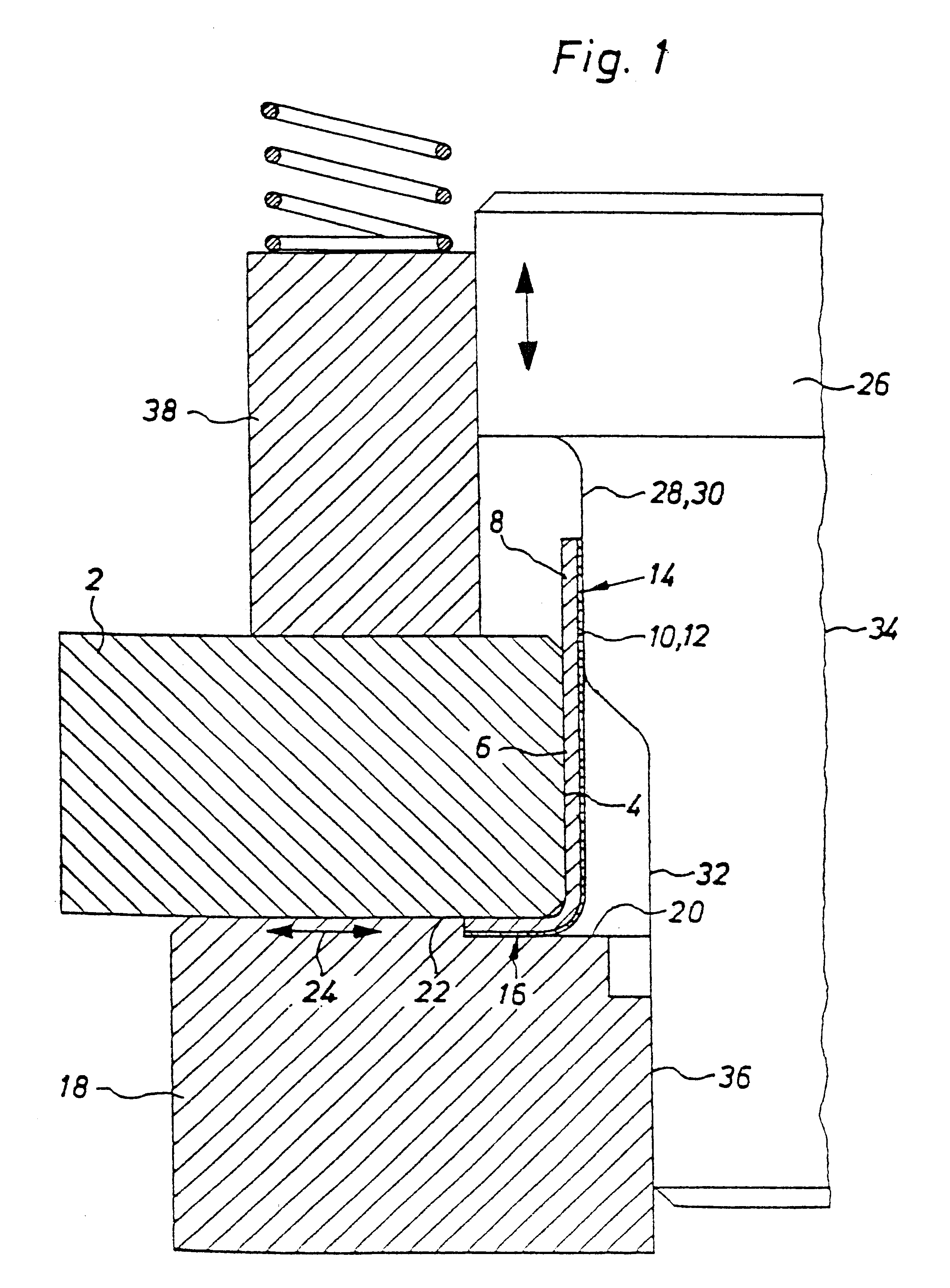
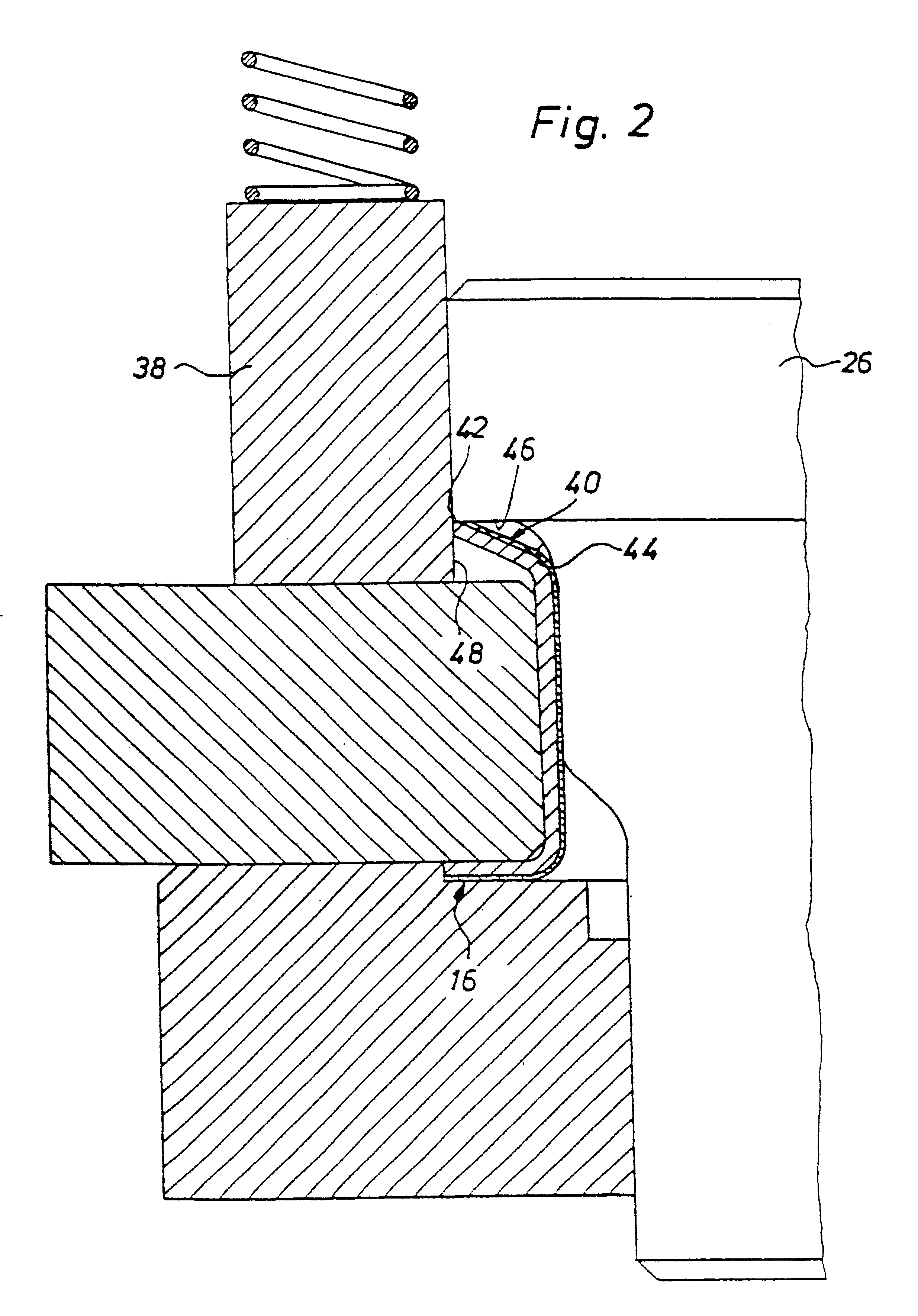
It proves furthermore to be advantageous if the mandrel used for this procedure is provided with a press surface running parallel to the flange surface to be created, and if the cylindrical area of the mandrel outer surface is curved where it meets this press surface, so that the end face of the cylindrical part of the flange bushing is guided by means of this curved section as far as a radial external stop, and as a result the upsetting of the cylindrical part of the flange bushing is achieved.

Problems solved by technology

It is not possible to loosen the bearing pin subsequently.
Production of this slide bearing is intricate, and, when the bearing pin is inserted, the corrugated profile becomes plastic, specifically, it is deformed under shear load.
The sliding surface is destroyed and the service life of the slide bearing is unsatisfactory.

Method used


Image

  • Slide bearing and method for the production thereof
  • Slide bearing and method for the production thereof
  • Slide bearing and method for the production thereof

Examples


Embodiment Construction

FIG. 1 shows a half-section drawing of an inventive slide bearing. The slide bearing comprises a hinge housing component 2 with a bearing opening 4 and flange-bearing bushing 6 pressed into it. The bearing bushing 6 is made from a steel-plastic-composite material. A porous bronze layer is sintered onto a steel backing 8, and a plastic slide bearing mixture 12 on a PTFE base is introduced into the pores of the bronze layer 10. The flange-bearing bushing 6 comprises a cylindrical part 14 and a first flange 16. The flange-bearing bushing 6 is pressed into the bearing opening 4. The flange 16 is held by means of a die press 18, with a press bearing surface 20 matching the flange, against a hinge housing component surface 22 which is adjacent to the opening 4. As a result, the flange 16 is held fast in the direction of the double arrow 24 as well, that is to say, in the surface plane direction of the surface 22. A mandrel 26 is inserted into the opening of the flange-bearing bushing 6. T...


PUM


Abstract

The invention relates to a slide bearing comprising with a bearing opening (4) pertaining to a hinge-housing component (2) and a flange bearing box (6) pressed into said bearing opening (4), whereby a bearing pin (26) can be inserted and rotated therein. Said flange bearing box (6) has a crimped projection (50) which projects radially inwards in the direction of the periphery. In order to create a slide bearing which can be preassembled, said slide-bearing is formed such that said crimped projection (50), when viewed from a longitudinal section of the box forms as a curved region (52) in the wall of said flange bearing box (6) in the vicinity of the axial end of the bearing opening (4) and said curved region (52) projects into the flange (16) of the box (6) in such a way that a space (h) is created between the opening (4) and of the bearing outer side which faces the flange bearing box (6) in the region of the curved profile prior to insertion of the bearing pins (26). The curved region (52) of the flange bearing box (6) can be radially deformed radially in an outward direction.

Description

BACKGROUNDThe invention relates to a slide bearing comprising a hinge housing component having a bearing opening and a flange-bearing bushing pressed into the bearing opening, into which a bearing pin can be inserted and pivoted therein, where the flange-bearing bushing has a crimped protrusion projecting radially inward along the periphery.The term 11 hinge housing component 11 is to be understood in the broadest sense. It can be a hinge or articulated arm which interacts with another articulated arm or hinge arm and on which a component to be swung, for example, an automobile door, can be attached. A stationary hinge plate or one attached to a piece of equipment which has a bearing opening to insert a bearing pin can also act as a hinge housing component. The bearing pin itself can be already tightened or be tightened down later to an additional hinge housing component, or with an object opposite the first one which is to be swung.A slide bearing of this type is known from DE 84 3...

Claims


Application Information

Patent Timeline
Patent Type & Authority Patents(United States)
IPC IPC(8): E05D9/00E05D5/14E05D5/12E05D5/00F16C33/08F16C33/04B21D53/40F16C33/14
CPCE05D5/127E05D5/14F16C33/14F16C33/08E05D9/00
Inventor STORCH, THOMASWAGNER, HEINRICH
Owner GLEITLAGER
Learn More