Ultra-micro gas turbine

a gas turbine and ultra-micro technology, applied in the field of ultra-micro gas turbine engines, can solve the problems of not being very typical and efficient engines, and achieve the effects of improving efficiency, reducing internal flow velocity, and increasing the efficiency of micro-scale turbine engine apparatus

Inactive Publication Date: 2011-05-03
BOARD OF TRUSTEES OPERATING MICHIGAN STATE UNIV
View PDF15 Cites 23 Cited by
  • Summary
  • Abstract
  • Description
  • Claims
  • Application Information

AI Technical Summary

Benefits of technology

[0005]In accordance with the present invention, a new approach in increasing the efficiency of a micro scale turbine engine apparatus is provided. In another aspect of the present invention, an ultra micro gas turbine engine includes a wave rotor. In various embodiments, an ultra micro gas turbine engine of the present invention includes a rotating disk which has a compressor, a wave rotor and a turbine, a first stationary member which includes an inlet and a first wave rotor port end plate, a second stationary member which includes an outlet and a second wave rotor port end plate and a combustion chamber which includes a fuel inlet and an igniter. Also provided are methods of microfabrication of an ultra micro gas turbine engine employed with other aspects of the present invention. An additional aspect of the present invention allows ultra micro gas turbine engines to be manufactured from materials that include silicon. In addition, a further aspect of the present invention provides a wave rotor with cells that are less than 1 cm in length.
[0006]The ultra micro gas turbine apparatus of the present invention is advantageous over conventional devices in that the present invention is expected to significantly improve efficiency, lower internal flow velocity, use shock wave compression and achieve reliability through redundancy while being extremely small in size. It is also believed that the present invention provides realistic, predictive modeling. The microfabricating processes employed with the present invention allow for a significant size reduction over conventional casting, drilling and machining methods. The ultra micro size of the present apparatus and its extremely small wave rotor channel lengths are ideally suited for use in ultra micro gas turbines, which leads to improved cycle efficiencies. Furthermore, the mirofabricated wave rotor of the present invention should be considerably more efficient than a microfabricated compressor, for example. Further advantages and areas of applicability of the present invention will become apparent from the detailed description and appended drawings provided hereinafter. It should be understood that the detailed description and specific examples, while indicating the preferred embodiment of the invention, are intended for purposes of illustration only and are not intended to limit the scope of the invention.

Problems solved by technology

Although gas turbine engines may be produced at a micro scale, such engines are not efficient and are not very typical.

Method used


Image

  • Ultra-micro gas turbine
  • Ultra-micro gas turbine
  • Ultra-micro gas turbine

Examples


Embodiment Construction

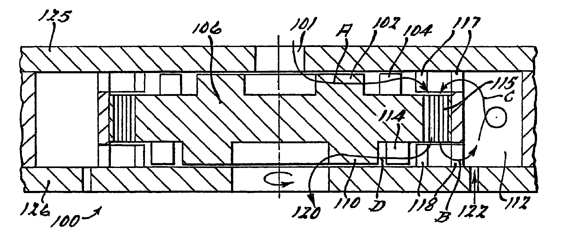
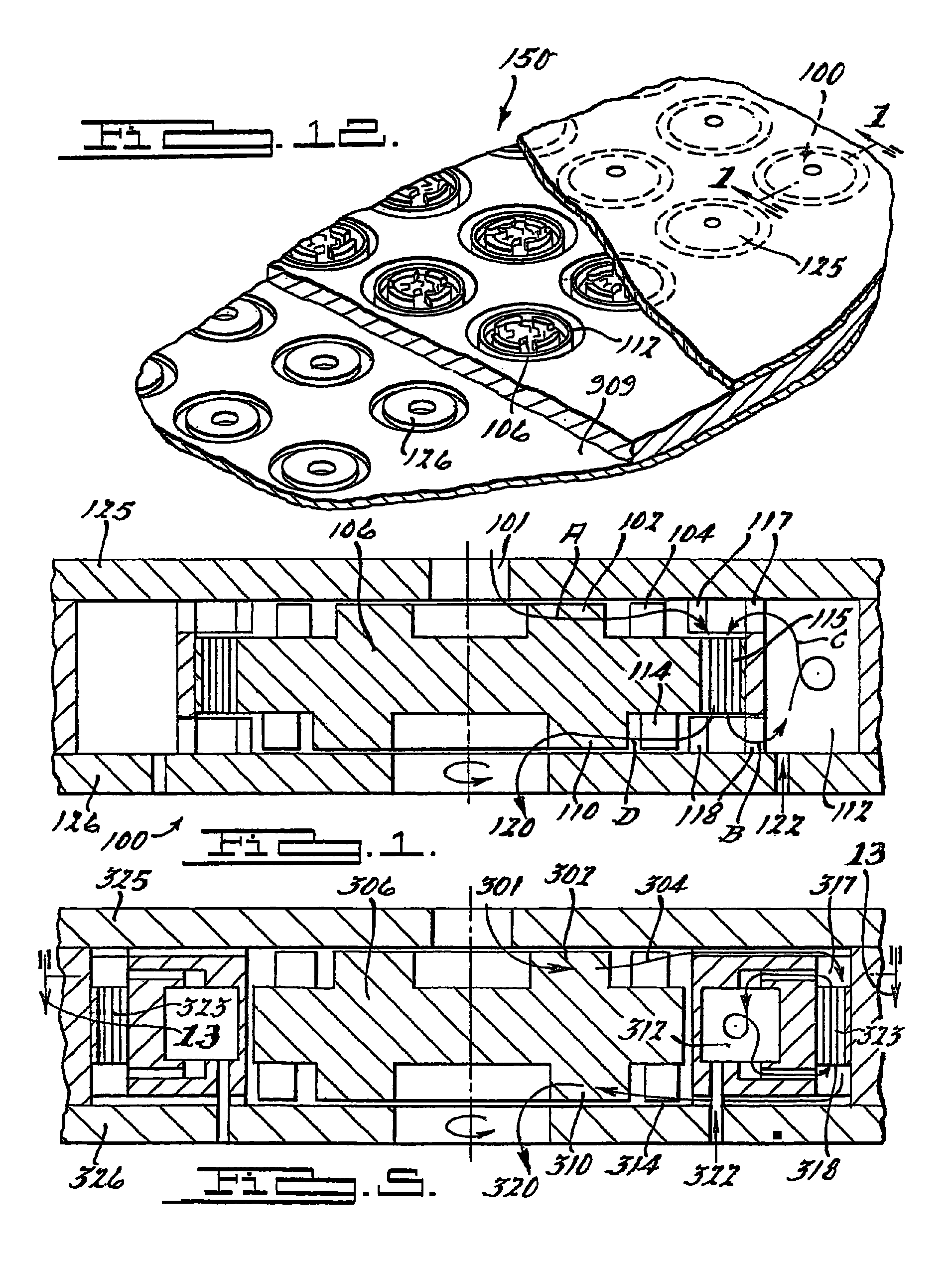
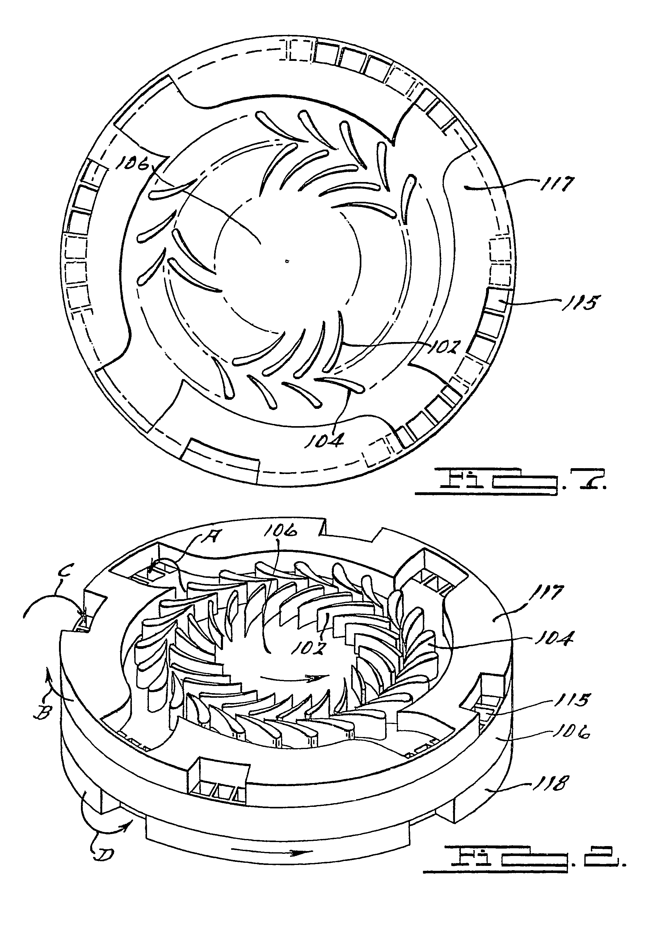
[0029]The following description of the preferred embodiments is merely exemplary in nature and is in no way intended to limit the invention, its application, or uses. The present invention provides methods and apparatuses for microscale gas turbine engines. The following definitions and non-limiting guidelines must be considered in reviewing the description of the invention set forth herein.

[0030]The present invention enables realization of a wide range of micro turbomachine componentry for producing sources of power, propulsion, and thermodynamic cycling that achieve high component efficiencies at sizes on the order of microns to millimeters. The micro turbomachinery of the present invention is dependent on fabrication of precise microstructures capable of operation at high temperatures and at high material stress levels. While the names and general functions of the micro turbomachinery of the invention are similar to that of conventional large scale turbomachinery, the specific de...


PUM


Abstract

The present invention provides an ultra micro gas turbine engine which includes a wave rotor. In various embodiments, the ultra micro gas turbine engine of the present invention includes a rotating disk which has a compressor, a wave rotor and a turbine, a first stationary member which includes an inlet and a first wave rotor port end plate, a second stationary member which includes an outlet and a second wave rotor port end plate and a combustion chamber which includes a fuel inlet and an igniter.

Description

CROSS REFERENCE TO RELATED APPLICATIONS[0001]The present application claims priority to U.S. provisional patent application Ser. No. 60 / 586,991, filed Jul. 9, 2004, and U.S. provisional patent application Ser. No. 60 / 627,742, filed Nov. 12, 2004, both of which are incorporated by reference herein.FIELD OF THE INVENTION[0002]The present invention relates to gas turbine engines, both apparatuses and methods of use, and more specifically, to ultra micro gas turbine engines.BACKGROUND OF THE INVENTION[0003]Gas turbine engines are essentially simple devices having only three parts: a compressor, a combustion area, and a turbine. Applications of such engines are well known, for example, in jet engines on commercial and military aircraft, the propulsion system for M-1 tanks, and small industrial power plants. Depending on the application of the gas turbine engine, the turbine can be used to produce thrust, rotate a drive shaft, or rotate a generator to produce electricity. Devices such as ...

Claims


Application Information

Patent Timeline
Patent Type & Authority Patents(United States)
IPC IPC(8): F02G1/00F02G3/00
CPCF01D1/12F02C3/05F02C5/10F05D2230/14F05D2250/84F05D2260/963F05D2250/82
Inventor MULLER, NORBERTIANCU, FLORIN VALCRIUAKBARI, PEZHMAN
Owner BOARD OF TRUSTEES OPERATING MICHIGAN STATE UNIV
Why Eureka
Try Eureka