Polishing apparatus and polishing method

a technology of polishing apparatus and substrate, which is applied in the direction of grinding machine components, testing/measurement of semiconductor/solid-state devices, manufacturing tools, etc., can solve the problems of “rounded edges”, insufficient polishing or excessive polishing, etc., and achieve the effect of quick and secure release of substra

Active Publication Date: 2015-08-11
EBARA CORP
View PDF23 Cites 4 Cited by
  • Summary
  • Abstract
  • Description
  • Claims
  • Application Information

AI Technical Summary

Benefits of technology

[0020]A first object of the present invention is to provide a polishing apparatus and a polishing method capable of quickly and securely releasing a substrate, such as a wafer, from a substrate holder, such as a top ring, after the substrate is polished.
[0021]A second object of the present invention is to provide a polishing apparatus and a polishing method capable of reliably detecting release of a substrate from a substrate holding surface.

Problems solved by technology

When polishing the wafer, if a relative pressing force applied between the wafer and the polishing pad is not uniform over the surface of the wafer in its entirety, insufficient polishing or excessive polishing would occur depending on the pressing force applied to each portion of the wafer.
As a result, the pressing force becomes non-uniform in an edge portion of the wafer during polishing of the wafer.
Such non-uniform pressing force would result in so-called “rounded edge” which is excessive polishing that occurs only in the edge portion of the wafer.
However, since the wafer is separated as a result of deformation of the membrane, a central portion of the wafer may fail to be separated from a corresponding central portion of the membrane which is not deformed greatly.
As a result, it is not possible to quickly release the wafer W.
As a result, fine interconnects formed on the wafer may be fractured or the wafer itself may be damaged.

Method used


Image

  • Polishing apparatus and polishing method
  • Polishing apparatus and polishing method
  • Polishing apparatus and polishing method

Examples


first embodiment

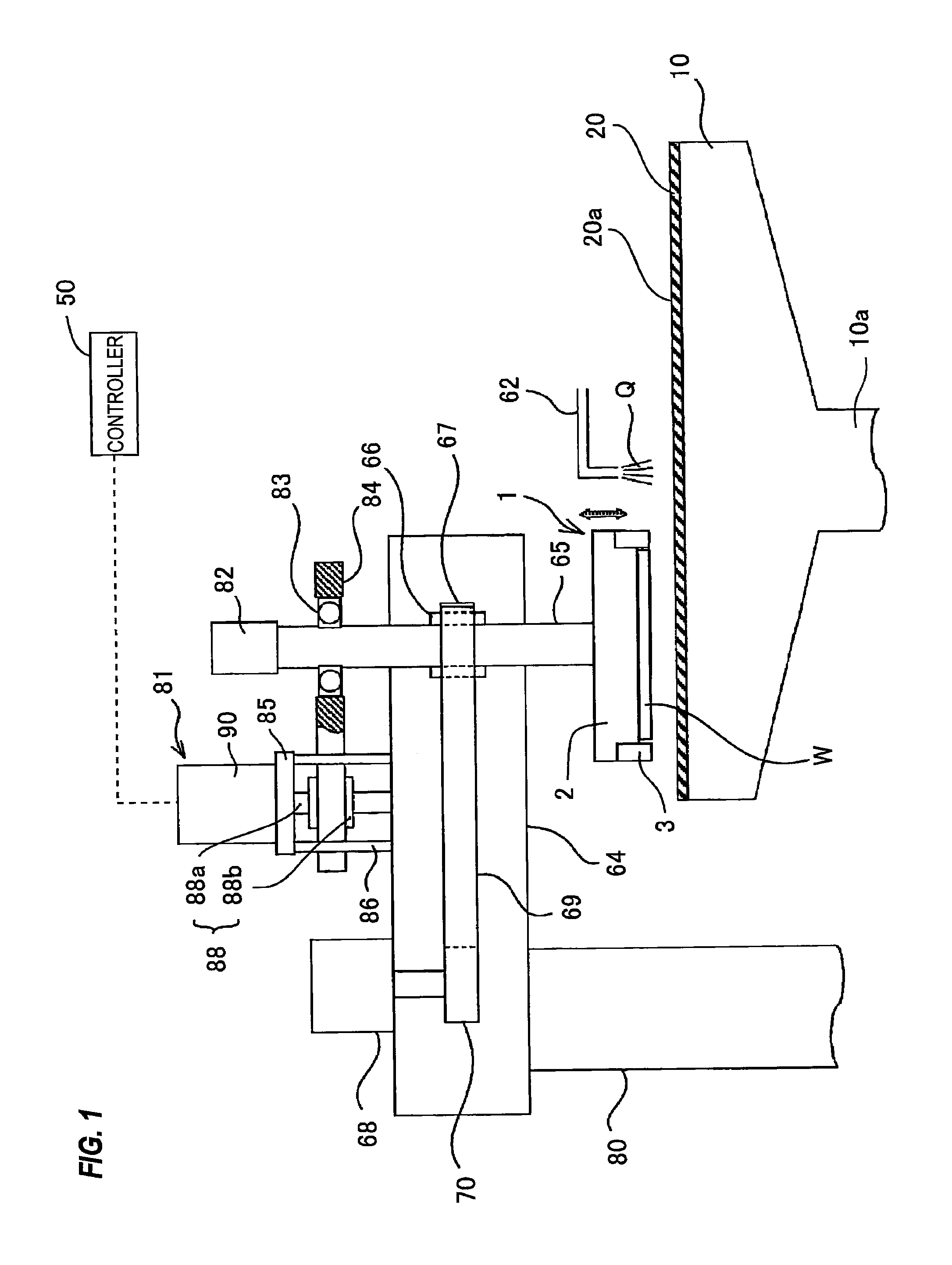
[0045]FIG. 1 is a schematic view showing an entire structure of a polishing apparatus according to the As shown in FIG. 1, the polishing apparatus includes a polishing table 10, and a top ring (a substrate holder) 1 for holding a substrate, such as a wafer, as an object to be polished and pressing the substrate against a polishing pad 20 on the polishing table 10.

[0046]The polishing table 10 is coupled via a table shaft 10a to a motor (not shown) disposed below the polishing table 10. Thus, the polishing table 10 is rotatable about the table shaft 10a. The polishing pad 20 is attached to an upper surface of the polishing table 10. An upper surface of the polishing pad 20 serves as a polishing surface 20a for polishing a wafer W. A polishing liquid supply nozzle 62 is provided above the polishing table 10 to supply a polishing liquid Q onto the polishing pad 20 on the polishing table 10.

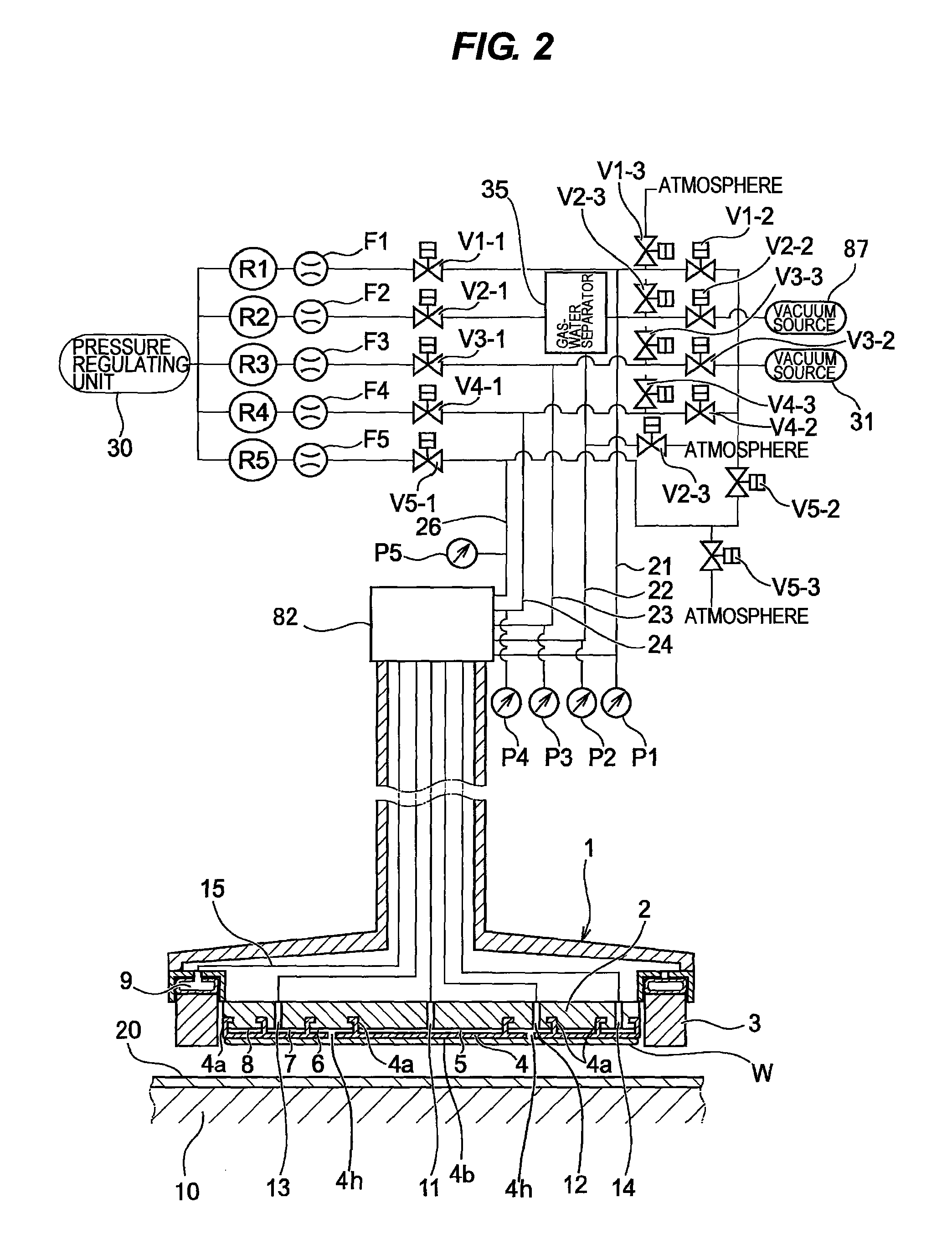
[0047]The top ring 1 includes a top ring body 2 for pressing the wafer W against the polishing su...

second embodiment

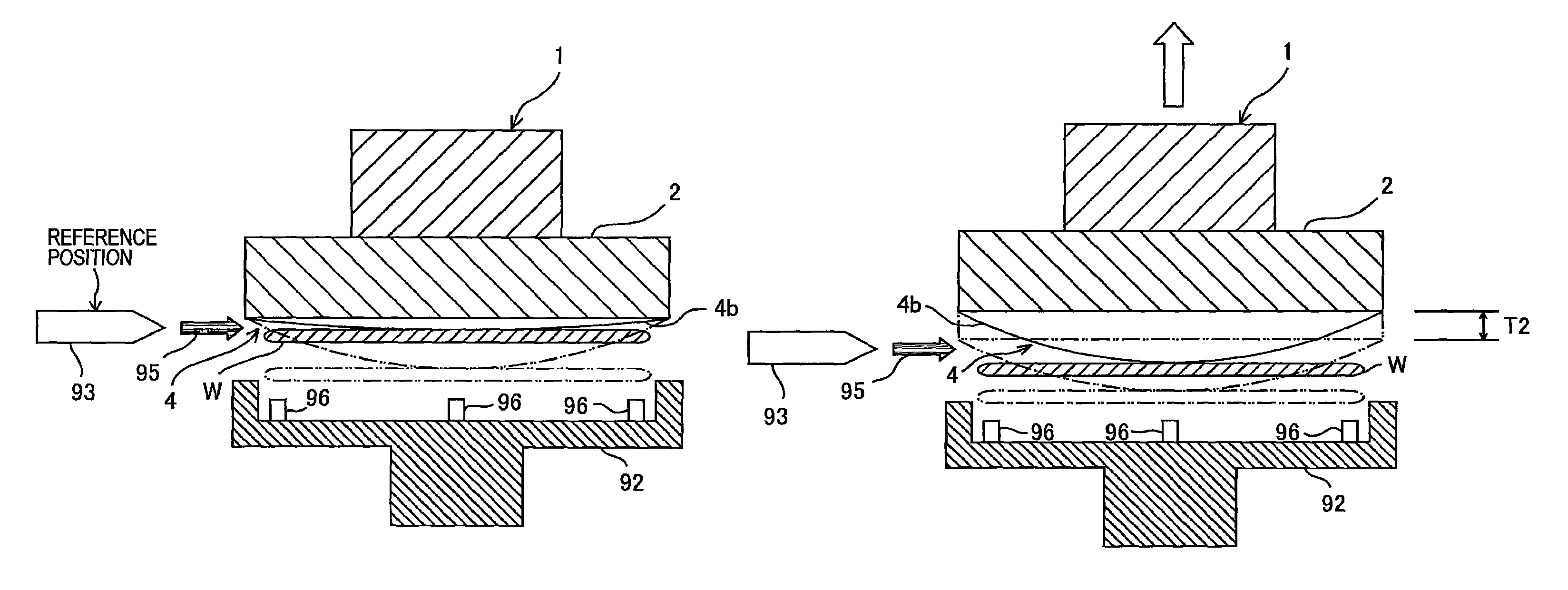
[0072]In a second embodiment, the controller 50 may use a cumulative value of the flow rate of the fluid flowing into the central chamber 5 for determining whether or not the wafer W is released from the membrane 4 and / or the amount of stretch h of the membrane 4. The cumulative value of the flow rate from when the releasing operation of the wafer W is started corresponds to the increased volume ΔV of the central chamber 5. Therefore, the amount of stretch h can be calculated by dividing the increased volume ΔV by the horizontal cross-sectional area S of the central chamber 5. The controller 50 calculates the amount of stretch h from the values of ΔV and S and determines the distance T2 from the amount of stretch h. The distance T2 may be equal to or smaller than the amount of stretch h.

[0073]The amount of stretch h can be calculated as follows. First, the valve V1-3 is closed so as to shut off the communication between the passage 21 and the atmosphere. Next, the pressure regulator...

fourth embodiment

[0078]As shown in FIG. 9, the release nozzle 93 is mounted to an elevating device (a vertically moving device) 98, which is configured to elevate and lower the release nozzle 93. Operations of the elevating device 98 are controlled by the controller 50. In the fourth embodiment, instead of elevating the top ring 1, the release nozzle 93 is lowered to a position of the contact portion between the wafer W and the membrane 4. Since the release nozzle 93 is lowered by the distance T2 from the predetermined reference position (see FIG. 3A) while the top ring 1 is not elevated, the fluid 95 from the release nozzle 93 can impinge on the contact portion between the wafer W and the membrane 4 accurately. Therefore, it is possible to release the wafer W from the top ring 1 quickly and reliably. The release nozzle 93 may be disposed below the reference position. In this case, the release nozzle 93 is elevated by the distance T2.

[0079]FIG. 10 shows a fifth embodiment of the polishing apparatus....


PUM


Abstract

A polishing apparatus includes: a polishing table for supporting a polishing pad; a substrate holder having a substrate holding surface and a pressure chamber formed by a flexible membrane, the substrate holder being configured to hold a substrate on the substrate holding surface and press the substrate against the polishing pad via pressure in the pressure chamber; a substrate separation assisting device configured to eject a fluid to a contact portion between the substrate and the flexible membrane so as to release the substrate from the substrate holding surface; and a vertically-moving mechanism configured to vertically move the substrate holder. The substrate holder is moved vertically in accordance with an amount of descent of the contact portion and then the substrate separation assisting device ejects the fluid to the contact portion.

Description

CROSS REFERENCE TO RELATED APPLICATIONS[0001]This document claims priorities to Japanese Patent Application Number 2012-149414, filed Jul. 3, 2012 and Japanese Patent Application Number 2012-155204, filed Jul. 11, 2012, the entire contents of which are hereby incorporated by reference.BACKGROUND OF THE INVENTION[0002]1. Field of the Invention[0003]The present invention relates to a polishing apparatus and a polishing method, and more particularly to a polishing apparatus and a polishing method for polishing a substrate, such as a wafer.[0004]2. Description of the Related Art[0005]With a recent trend toward higher integration and higher density in semiconductor devices, circuit interconnects become finer and finer and the number of levels in multilayer interconnect is increasing. In the fabrication process of the multilayer interconnect with finer circuit, as the number of interconnect levels increases, film coverage (or step coverage) of step geometry is lowered in thin film formati...

Claims


Application Information

Patent Timeline
Patent Type & Authority Patents(United States)
IPC IPC(8): B24B49/00B24B37/30H01L21/66
CPCH01L22/12B24B37/30
Inventor NAKAMURA, AKIRA
Owner EBARA CORP
Why Eureka
Try Eureka