Safety system for a traction kite with releasable adjustable bar stopper

a safety system and adjustable technology, applied in the direction of marine propulsion, special-purpose vessels, vessel construction, etc., can solve the problems of re-assembling the control system, carrying a high pulling load, and central load bearing line,

Inactive Publication Date: 2015-04-23
OCEAN RODEO SPORTS
View PDF8 Cites 3 Cited by
  • Summary
  • Abstract
  • Description
  • Claims
  • Application Information

AI Technical Summary

Benefits of technology

The present invention provides a kite control system with a releasable bar stopper that allows for quickly and securely releasing of the bar stopper, without the need for disassembling the central load bearing line from the rider or a secondary safety line. The system includes a wear eliminating cover tubing with multiple discrete bar stopper positions, a bar stopper that can be easily moved to a position of choice, and a simple method for exposing the length of central load bearing line inside the tubing for inspection. The central load bearing line is adapted with a connection loop for connecting it to a hook or another loop on a pilot's harness or a fixed point on a vessel, and a bar stopper arrangement that restrains the motion of the control bar to the section of line between the system hub and the bar stopper. The bar stopper is retained to the system hub by a retaining means which can be released by a primary safety quick release mechanism, allowing the control bar to slide along the central load bearing line towards the kite to reduce the power of the kite to a safe level. The invention offers multiple safety release methods to instantly depower the kite and an easily operated position adjustable bar stopper.

Problems solved by technology

A disadvantage of releasing the central load bearing line from the harness hook for emergency releasing is that the central load bearing line may at the moment of releasing carry a high pulling load.
Releasing the kite like this can cause the control bar to shoot up in to the direction of the kite, not seldom causing the lines to twirl and tangle to a point that re-assembling the control system becomes too complicated for the situation of the rider.
The repeated movement of the control bar sliding over the central load bearing line usually causes wear on this line and in side the bar hole.
Even though wear-resistant line is used, this wear can lead to breakage and therewith dangerous situations.
Some surf kite control systems have the secondary safety line running outside the tubing, making it subject to wear, whereas some other have the secondary safety line running through the tubing, in which case measures need to be taken to avoid twisting of the main load bearing line and the secondary safety line internal to the tube.
Such an increment of tube diameter requires a larger bar-hole and therewith a wider bar section, which is unfavourable for a good grip.
Although the use of tubing eliminates wear of the lines caused by rubbing of the control bar, sand and debris may accumulate inside the tubing, causing wear which is typically hidden from view as the current kite control systems with tubing don't allow easy access to the portion of the lines running inside the tubing.
It needs to be mentioned that use of propulsive wings and traction kites involves a number risks, some of which already discussed above.
Pilot error as well a material error can cause serious injury and even death as the forces produced by kites and quickly amount to dangerous levels.
Designing kites and kite control systems needs to involve very serious failure analysis of every part.

Method used


Image

  • Safety system for a traction kite with releasable adjustable bar stopper
  • Safety system for a traction kite with releasable adjustable bar stopper
  • Safety system for a traction kite with releasable adjustable bar stopper

Examples


Embodiment Construction

Best Mode

MODE FOR THE INVENTION

Mode for Invention

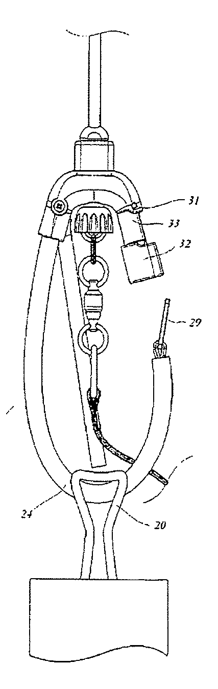
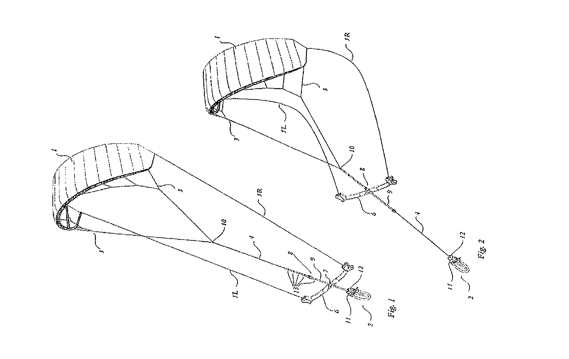
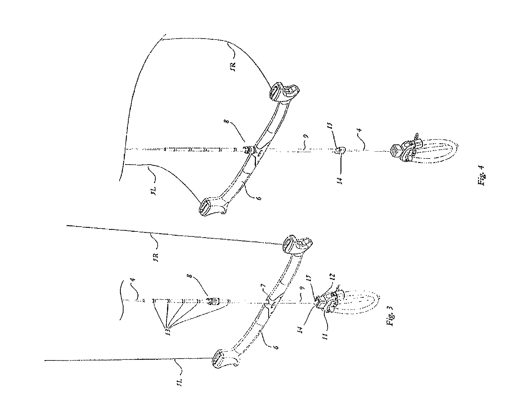
[0025]The present invention is further demonstrated by FIG. 1. A kite 1, with anchoring means 2, is provided with a typical 3-point control system which has multiple lines 3 attached to the forward edge which converge in to a central load bearing line 4 which attaches to the anchoring means 2, where the length of the lines 3 and central load bearing 4 together define length A, and two control lines SL and SR, attached to both ends of the trailing edge, each attached to one end a control bar 6. The bar is provided with a centrally placed hole 7 through which the central load bearing line can slide. A releasable adjustable bar stopper 8 according to the present invention is attached to a retaining means 9 and situated between the control bar 6 and a stopper ball 10. The retaining means attaches releasable to a system hub 11 of the anchoring means, provided with a release cuff 12. In general use, the flying kite is controlled by movement...


PUM


Abstract

A safety system for a traction kite comprises a central load bearing line and sliding control bar arrangement comprising a connection loop for connection to a harness hook, a system hub connecting the loop to the central load bearing line and a bar stopper located along the load bearing line towards the kite relative to the control bar. The bar stopper is retained to the system hub by a retainer which can be released by a primary safety quick release mechanism in such a way, that engaging the primary safety mechanism allows the control bar to slide along the central load bearing line towards the kite to reduce the power of the kite to a safe level.

Description

TECHNICAL FIELD[0001]The present invention relates to rider control systems for propulsive wings and sport traction kites. More particularly the present invention relates to a kite control bar stopper adjusting and retaining system that allows the rider to quickly and reliably adjust the bar stopper position and release the bar stopper to remove the power from the kite.BACKGROUND ART[0002]Using a kite for wind-driven propulsion of water, land, ice or snow-craft is highly effective and simple compared to other means of wind driven propulsion like sails and turbines. A kite can be constructed in such a way that all or most of the pulling force enters the craft in one point, without resulting momentum that can tip the craft over and without the requirements for rigid elements like masts, poles, and shafts connected to the craft. Kite are flying remote from the craft, in air layers with stronger winds, and can fly in figures across the sky in order to generate apparent wind, thus increa...

Claims


Application Information

Patent Timeline
IPC IPC(8): B63H9/06
CPCB63H2009/0692B63H9/0685B63H8/16B63H9/072B63H8/18
Inventor ENSERINK, ANTON RUDOLF
Owner OCEAN RODEO SPORTS
Why Eureka
Try Eureka